BASF Boiler Plant Upgrade to Today’s Technology
Do you want this article in PDF format? Download it here:
Download a PDF1. FINAL GOALS FOR THE PROJECT
The goals for upgrading the boiler plant system were to achieve the highest degree of safety, system optimization, high reliability and an energy efficiency with today’s technologies. Along with these goals was to also create a work environment that is highly desirable to work in for plant operations and plant personnel. With the boiler upgrade, other aspects of the system were reviewed and upgraded such as the associated support equipment, which included the deaerator, blowdown and chemical systems.
2. EXISTING BOILER PLANT OPERATION
The two existing boilers at the BASF facility was manufactured by York Shipley, Inc. in 1981 and were a firetube design with a capacity of 300 boiler horsepower each. The boilers operated admirably during their 40-year service, however with age the boilers came along occurring failures that required more attention by maintenance. With renovations and improvements downstream came a large reduction in steam output needs. The boilers, being limited on steam output turndown, began short cycling in the summer and winter. The on/off operation resulted in more stress on the boiler and burner equipment and a reduction in overall energy efficiency of the system.
The existing spray deaerator was not meeting ASME dissolved oxygen requirements of 7 pbb. This was resulting in an increase in non-condensable gases. With these elevated non-condensable gases in the system, higher corrosion rates of internal piping and infrastructure can occur. All other associated equipment such as blowdown tank, chemical feed system, makeup water meters and steam flow meters were deemed to be older technologies and needed to be updated to the latest technologies.
3. ENGINEERING PROJECT SCOPE
Inveno Engineering, LLC senior steam team field engineer(s) and the Swagelok local support team were assigned engineering and design for the New Boiler Project. The project consists of engineering, design, full AutoCAD prints, equipment specifications, RFP’s and procurement recommendations. The engineering scope was to encompass the boiler selection process, boiler plant layout, code validation, specifications, vendor interviews, installation, startup and validation testing. Inveno Engineering, LLC engineers implemented the steam system team concept, which includes on-site engineers, on-site AutoCAD team, off-site technical personnel, off site support engineering, technical writers, and support staff. The Inveno Engineering, LLC team worked directly with the BASF team to ensure a successful project.
The steam system engineering team goals were to accomplish.
- Safety
- Reliability
- Plant optimization
- Energy efficiency
- High turn down to meet plant steam requirements
- Latest technologies in boiler control and management
- Proper deaerator operation with newest control system
- Chemical treatment
Another part of the project was to develop a detailed Steam System Balance thus ensuring that the new boilers will meet and exceed the steam system requirements.
4. CODES
An essential part of the project is to ensure all codes are strictly followed to ensure a safe operation for everyone involved. The following codes were adhered to during the entire project, Boiler ASME, B31.9, B31.1 ASME pressure vessels, B16.1, etc.
5. NEW BOILERS (FIRETUBE VS. WATERTUBE)
One of the first steps in deciding on new boilers is to determine the operational design of the boiler. Two boiler designs considered were the firetube design and the watertube design. All boilers have their positive features and negative features therefore the Inveno Engineering steam team and BASF reviewed all aspects of operation including their loads and run conditions and decided to proceed with a watertube design boiler. The firetube boiler design was eliminated due to several considerations. One is the installation consideration for a firetube boiler that requires additional space for boiler tube replacement if required after years of operation. The other negative consideration is the thermal losses off of the exterior casing of the firetube boiler, specifically, the back wall area. The firetube boiler back wall would have high elevated temperatures in excess of 300oF thus an energy loss in excess of $25,000 a year. Safety concerns for plant personnel with high surface temperatures and OSHA requirements for plant personnel protection for areas of greater than 140 degrees F. Insulating the firetube back wall presented several operational issues, such as having to remove the insulation regularly for annual boiler inspections.
The watertube boiler presented a much smaller footprint and also ease of accessing the boiler internals for any maintenance. Watertube boiler provides better compensation for expansion and contraction thus providing a longer operational life expectancy. The combination of the boiler and a burner design allowing for 10 to 1 turn down with the addition of the latest control technology provided the perfect combination for this specific application.
6. CONTROL SYSTEMS
The boiler control system design was selected to be a parallel positioning control with oxygen trim was determined to be the best control scheme for the boilers. Parallel positioning systems offer key design benefits over the other control schemes for this size of boiler operation. One actuator positions the fuel control valve(s) while a second actuator positions the air control damper. Each combustion actuator is equipped with a position re-transmitter for cross limiting purposes to ensure a proper fuel air mixing. The parallel positing system allows for proper tuning of the fuel air ration for each firing rate demand, typically at each 10% of the firing curve.
Figure 1: SAMA Drawing for the Combustion Control System.
Oxygen trim system adjust for any factors that may affect the fuel air ratio curve and adjust according to keep the combustion at peak performance.
Advantages for this control scheme:
- Allows electronic characterization of fuel/air ratio
- Boiler will have variable speed drives which mates to this control scheme
- Provides large turndown
- Oxygen trim is easily being accomplish
The control system and the burner management system were to be accomplished by a PLC’s and to provide all-relevant data and operational parameters for the plant personnel. The boilers, DA tank, and flow meter data were setup to connect to the site’s building automation system, notifying personnel of key alarms and allowing for energy tracking of consumed resources (e.g. natural gas, makeup water, steam output).
7. FUEL AIR RATIO – COMBUSTION PROCESS
The combustion fuel-air ratio curves are derived from a combustion testing process and is very important in the overall boiler efficiency. Lower oxygen levels which is in direct relationship to the quantity of excess air that is required for the combustion process. To achieve complete combustion, a portion of combustion air has to be available for the combustion process that exceeds the stoichiometric amount needed to complete the combustion process. The ratio of the excess combustion air to the theoretical amount of air required is called the excess air.
Due to the characteristics of the burner, the excess air levels are curved from low fire which has higher excess air levels (oxygen levels) on a curve up to high fire that has lower excess air levels.
Unfortunately, if more excess air added to the combustion process results in lower combustion efficiency. The combustion process/burner is taking ambient air for the oxygen that is needed in the combustion process, but it has to heat up all the other gases in the ambient air such as the large quantity of nitrogen. All combustion air will be increased to temperatures above 2600oF and higher which is the flame temperature.
The new burner technologies allow the burner to operate a lower or reduced excess air in the combustion process and another benefit is the flue gas exit volume is reduced. Lower excess air levels reduce the temperature of the flue gas and a reduction in gas velocities. The flue gas velocity reduction allows the gas to spend more time in the boiler, where the heat energy can be absorbed. The fuel-air curves for each of the boilers is shown in the following graphs that indicate the curves with the older boilers vs. the new boilers.
Figure 2: No. 1 Boiler Fuel Air Ratio Curves with the Older Boilers vs New Boilers.
The fuel-air curves for each boiler indicate the significant reduction in excess air levels thus improving the boiler efficiency.
Figure 3: No. 2 Boiler Fuel Air Ratio Curves – Old Boiler vs. New Boiler.
The economics are very attractive for keeping a boiler operating at peak performance with respect to the optimum fuel-air ratio curve. BASF has the ability to monitor the fuel ratio’s and has Clever Brooks local technical support team check the operation on a periodic bases to ensure the optimal performance.
8. ENERGY EFFICIENCY GAINS
The energy efficiency gains for installing new boilers and deaerator system are based on several items;
High boiler efficiencies
- 2% (older boilers) vs. 83.9% (new boilers)
- Lower excess air levels in the fuel/air ratio
- Energy losses from a on/off operation (older boilers) vs. continuous operation with the new boilers (higher turndown)
- Lower thermal losses with the new boilers
- No high temperatures from any side of the new boilers compared to the older boilers high back wall temperatures
- Less boiler outside surface area than the older boilers, thus reduce thermal losses
- More efficiency boiler chemistry
- Lower blowdown losses
Insulation
- Reduction in thermal losses from deaerator, steam and condensate piping, blowdown tank, etc.)
- Increase in the steam system thermal cycle efficiency of 12.8.%
9. DEAERATOR (SPRAY VS. TRAY DESIGN)
The new deaerator design was required to provide a feedwater dissolved oxygen content of no greater than seven parts per billion and operate at steam pressure of 8 psig with a 20-minute feedwater storage time for the boiler operation. Reviewing the two deaerator design choices, the spray type and tray type design. Both deaerator types can provide the performance standard that was dictated by the engineering RFP’s. However due to height considerations of the existing boiler plant it was decided to proceed with a spray type deaerator which had a lower height requirement and maintained the required NPSH for the boiler feed pumps. The control system for the deaerator was another area where the plant needs to have control of the steam pressure, feed pumps and monitor points the critical points in the system.
10. INSULATION
Keeping with the proactive insulation-management program was critical to overall boiler plant system to maintain a high steam system thermal-cycle efficiency. Furthermore, because boiler components (deaerator, blowdown tank, etc.) operate above 212°F (100°C) can have a negative effects of uninsulated control components and energy loss are unacceptable in today’s industrial boiler operation.
What items in a boiler plant and system needs to be insulated? The simple answer is everything! Insulating the steam lines is not sufficient in today’s boiler plant operation. Therefore, the deaerator, steam line, condensate lines, blowdown tank and other boiler plant related components were insulated. All insulation was metal jacketed to ensure the long-lasting energy and safety effects of the insulation.
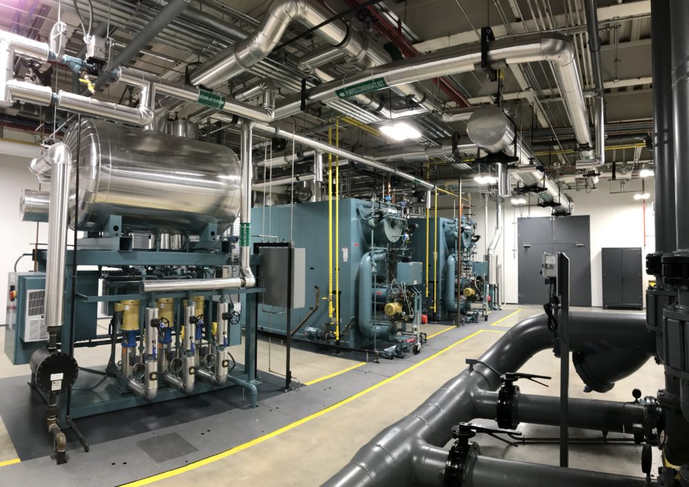
11. PLANT LAYOUT
The BASF philosophy and Inveno Engineering, LLC steam team is that the boiler plant needs to be free of all components that are not related to the boiler operation. The boiler plant is not a storage area, but it is an area where the combustion process is occurring with a very combustible fuel. The other factors are to have a clean, well-organized, and well-lit environment for the boiler plant personnel which provides an excellent work environment and work habits. With this type of environment, the boiler plant will stay in this condition for the life of the boiler plant and plant personnel will take pride in their boiler plant.
We believe the final result in the final boiler plant is a boiler plant that is at World Class.
12. CHEMICAL SYSTEMS
One of the key factors in a boiler chemical program for a steam boiler operation is to be able to conduct daily steam/boiler samples for testing. The chemical program is a major factor to have a reliable and long operational life of the boiler and steam system. In any boiler plant sampling system, a central steam sampling location is a must for any boiler chemistry monitoring program. The next key factor for the steam sampling system was to ensure that all components are meeting the code requirements and designed for long reliable operation. Inveno Engineering, LLC steam team discovers that more than 37% of existing steam/boiler sampling system had code violations. Swagelok was able to provide a custom solution with a central sampling system that provide all aspects for code requirements and personnel safety. The central steam/boiler sampling system allows plant personnel to take the required samples with a safe and reliable operation. The new sample cooler utilized Swagelok tube fittings coming from the boilers and DA tank. The high-quality airtight fittings provided a robust test result of the dissolved oxygen testing for the deaerator. Testing to 7 ppb is an incredibly low dissolved oxygen level and the plant could not afford to question the testing results that could be influenced from air leakage from low quality tube fittings. The plant reduced the chemicals consumption from 3 down to 1. BASF implemented a new “Ultramine” program. This greatly simplified the maintenance of the chemical program, as the reduced chemical storage and handling as well as chemical pump failures.
13. FINAL MANUFACTURER SELECTION
One of the key factors in the final manufacturer final selection was the engineering support that the manufacturer could bring to the project. Another key factor was the technical local service support for all the boiler plant components. Any boiler plant operation needs to have the required technical support and service to ensure an energy efficient and reliable operation. Cleaver Brooks was selected to the be manufacturer for all the boiler plant equipment. Their equipment met all of BASF’s extensive requirements and they had a highly reputable local service team that would aide in the long-term upkeep of the new equipment.


