Sizing Steam Traps
My name is Kelly Paffel. I am Technical Manager for Inveno Engineering LLC, located in Tampa, Florida. We’re a domestic and international firm, doing engineering, specifically in steam and condensate systems. Today I want to talk about steam trap stations, more I want to talk about sizing process steam traps.
A proper steam trap. Important facts to remember:
Obtaining efficient and reliable steam trap operation. The correct operational design must be selected, sized properly and installed perfectly. Incorrect steam trap sizing will either cause condensate backup or steam loss. Improper sizing is one of the top three causes of premature failures.
When steam trap sizing the connection, size is not what we’re looking to size a steam trap on. What we’re looking to do is size the internal discharge orifice inside the steam trap. Example would be a two-inch steam trap can have the same condensate capacity as a 1/2-inch steam trap, what we need to determine is the condensate capacity and orifice size inside the steam trap. Then select the trap connection size to meet the installation requirements.
Data for proper steam trap sizing.
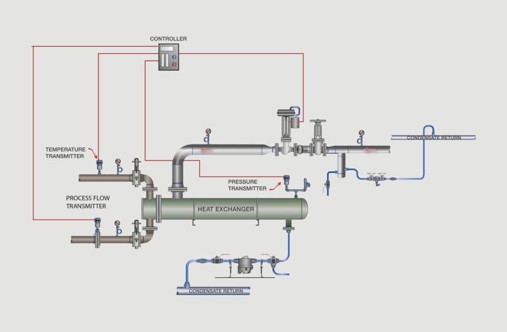
Determine the maximum pressure on the steam line supplying the process. We want to know the maximum steam pressure for the steam trap body rating and the maximum steam temperature. Again, everything that we put in the steam system, we must know the pressure and temperature rating. Therefore, we must also select the steam trap orifice to be able to operate at that maximum pressure. The maximum pressure is determined by the safety valve setting. Example would be this here. The operating pressure to the process as you can see is at 75 psi. The safety valve here is set for 150 psi. Everything in the system as to be rated for 150 psi.
Next, we want to determine the inlet pressure to the control valve. Documenting steam pressure at the control valve inlet is very important. Example, 100 psi operating steam line does not mean 100 psi at the control valve. There’s pressure drops in the system and we must know the different pressure drops. The next thing is determining the outlet pressure from the control valve to the process. There is a calculated pressure drop across the control valve, also there’s a calculated pressure drop through the heat exchanger. All heat transfer components have a pressure drop. The information can be obtained from the heat transfer performance sheets.
Going back to our example, again, is that we have 75 psi to the inlet of this valve, it doesn’t mean we have 75 psi down here. We have, let’s say a 15 psi drop across a valve and then we come into the heat transfer and then we’ll have a 10 psi drop across the heat exchange. Therefore, we end up with 50 psi on the inlet of the steam trap or what we call P4. The thing about that is that’s significantly different than looking at 75 psi for the inlet pressure, there’s a 25-psi difference and that can have a significant impact on the steam trap capacity.
Next, we’re going to calculate the inlet pressure to the steam trap, which we did. Subtract the heat transfer pressure drop from the steam control valve outlet pressure to determine the inlet pressure to the steam trap. Now, we’ve got to determine the outlet pressure at the discharge of the steam trap. One more thing we must calculate out the condensate flow rate. Maximum condensate capacity in pounds per hour and minimum condensate capacity in pounds per hour. We’re going back here to this example again, this system here that I have up here, is a modulating steam system. Any time we modulate steam, we want the condensate line to be zero psi. Out in the real world, plants need to have pressure gauges at the outlet of the steam trap, so we know what P5 is. We have found out what P4 is and we calculated for this example, let’s say a 1000 pounds per hour condensate capacity.
Now, we have quite a bit of information and we’re looking at choosing the correct sizing factor depending on the steam trap design.
The sizing factor for:
Inverted buckets: Three to One.
The sizing factor for:
The float and thermostatic: Two to one.
The sizing factor for:
Thermostatic: Three to one.
The sizing factor for:
Thermodynamic: Three to one.
What does that mean? We took the capacity times the sizing factor. We’re going to use a float and thermostatic design steam trap which is a mechanical family and is a continuous flow, which we want to have for process application. The sizing factor is two to one, so we calculate out a 1000 pounds per hour, take that times two, our steam trap must be able to handle 2000 pounds per hour at our Delta P. Calculating the minimum differential pressure across the steam trap, we already looked at that back here on our application. We said that we have 50 psi down here at the inlet and we said we’re going must zero psi down here at the outlet. We have a 50-psi differential across a steam trap.
Evaluate the condensate flow condition in the steam trap operation. There’re two types of steam traps, on/off operation for condensate discharge and continuous flow operation. Again, I said this is the process application and we’re going to utilize a continuous flow, which is a flow in thermostatic mechanical design steam trap.
Now, we determine the orifice size for the following data required. We determined the maximum steam pressure for our application was a 150 psi. The maximum steam temperature was 366 degrees. The operating pressure at the inlet to the control valve was 75 psi, inlet steam pressure of the steam trap, we said 50 psi. Once we subtracted the pressure drop across the heat exchanger and the pressure drop across the control valve, so we have 50 psi here. The thing is that our outlet P2, we said is zero psig. We have our differential pressure.
Now, I’ll go to a capacity chart and this happens to be a mechanical steam trap capacity chart. I’ll go across the top here and I’m looking for that differential. Right across here, as you can see, differential pressure. We’re going to comment, and we said 50 psi, we said our capacity was 2000 pounds per hour. I go down here ’til I find something greater than 2000 pounds per hour. I find 2460 pounds per hour. If I go over here, and the orifice is only rated for 50 psi, remember I said the orifice must be rated for the maximum pressure, which is a 150 psi. I must go back to my chart and continue down to see something greater than 2000 pounds per hour, with an orifice rated for 150 psi or higher. I come to right here and I will have this here orifice, which is a 150 psi. To get closer to the capacity, actual capacity of the steam trap, I might use a little bit higher pressure orifice, which gives me a little bit lower of a capacity and closer to the 2000 pounds I’m looking at.
Either case, these two steam traps would be the correct steam trap for this application, therefore the steam trap is properly sized. The other one for mechanical, is the inverted buckets and it works the same way as we were talking about the other application was flow and thermostatic and you have a differential pressure up here of 50 psi, you would go down to the chart, ’til you find something 2000 pounds per hour and make your selection of the orifice’s that are there.
The other thing to remember; there can be back pressure on to the condensate system and a high percentage of steam trap application will have pressure in the discharge side of the steam trap and that pressure may be unintentional or deliberately produced by the design of the system. Unintentional operation is elevating the condensate overhead into the pipe rack. For every foot, rises half a psi. Intentional back pressure is the design of the system and a lot of systems we will run under pressure. Know the condensate pressure, so you get the correct differential.
That concludes what I’m talking about, process applications. Here is our contact information. Please stop by and look at our new website, we have a tremendous amount of information up there.


