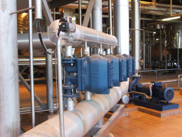
Steam Trap Station Management – Best Practice No. 4
Do you want this article in PDF format? Download it here:
Download a PDFBEST PRACTICE NO. 4
SUCCESSFUL STEAM TRAP MANAGEMENT
With today’s energy costs and demand for production reliability, it is extremely important to have a proactive steam trap station management program included with the overall steam system management program. A steam trap station failure rate must be below 3% annually. To achieve a reliable steam trap station system, root cause analysis has to be part of the program. We can no longer accept failures of more than 3% with steam trap station components. Today, plant operation mandates a steam trap station to be reliable for at least 6 years or longer.
Why steam trap station management instead of steam trap management? Steam traps are only one component in a proper steam trap station arrangement. Just reviewing the steam trap instead of the entire steam trap station can lead to an unsuccessful steam trap station management program.
Figure No. 1 Steam Trap Station Installation
Poor steam trap station management is a major cause of energy dollar losses and significantly increases emissions in today’s steam system operation. A successful steam trap station management program can identify defective steam valves, steam traps, strainer failures, and blowdown valve failures.
Additionally, with this documentation and knowledge, the amount of energy and emission impacts for each steam
valve or steam trap failure can be calculated.
A steam trap station program will accomplish the following:
- Reduce energy losses
- Increase system reliability
- Keep failure rates below 3% annually
- Decrease combustion emissions
- Decrease production downtime
- Improve steam quality
The return on the investment in a complete and integrated steam trap station management program typically takes less than 12 months. There are many steps in the road map to accomplish a successful program, but one important key to a successful program is to have all personnel involved in the program. We have listed the 17 steps to success on the next few pages.
Road Map to a Successful Steam Trap Station Management Program
1. What are the components of a steam trap station?
The first step is to define all of the components that make up a steam trap station.
- Isolation valves
- Strainer
- Blowdown valves
- Steam trap
- Test valve
- Check valve
i. In some applications
2. Who are the people that need to be involved?
A successful program must include the participation of people at all levels of the organization.
- Management:
A program needs commitment from management in providing resources - Energy person or department
- Environmental
- Maintenance management
- Maintenance personnel
- Utility department
- Plant engineering
- Corporate engineering
- Production
- Reliability
- Safety, What are the end results that will occur with a steam trap station management program
- Reduced energy usage
- Reduced emissions
- Increased reliability
- Increased production performance
- Improved safety
3. Select a steam team leader
The team leader must accomplish several things for the team members, including:
- Managing and coordinating the effort between all team members
- Communication
- Arranging the appropriate meetings
- Assuring the proper documentation is occurring
- Benchmarking for the system
- Coordinating all aspects of the program
- Defining the work efforts for the steam team
- Providing documentation on the project progress
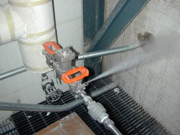
Figure 2: Excessive steam venting from steam trap station failures
4. Steam trap station management
What other items should the steam trap station management team address?
- Steam leakage detection and correction
i. To be carried out frequently
(1) Every six months
ii. Enhance proficiency - Gas leak detection and correction
i. To be carried out frequently
ii. Enhance proficiency - Steam safety valve
i. Ensure data is captured in the database
ii. Ensure preventive maintenance (PM)
5. Steam system training
Develop a road map to train the plant personnel on the different aspects of the steam system and its operation. Some examples of training topics include:
- Steam traps
- Root cause analysis
- Testing methods
- Problem solving
- Correct sizing
- Piping
- Installation
- Condensate recovery methods
6. Track the steam trap stations in a database
Do you know where your steam trap stations are located? All steam trap stations need to be identified with a unique identification code. Additionally, important information should be recorded on each steam trap station for future reference and entered into a database system for proper analysis.
- Examples of the information to be recorded during a steam trap station survey include:
- A map of all steam trap station locations
- Picture of the steam trap station, if possible
- Steam trap station number
- Location
- GPS location numbers
- Application
- Maximum steam pressure
- Minimum steam pressure
- Capacity
- Maximum
- Minimum
- Connection size
- Type of isolation valve
- Steam trap information
- Manufacturer
- Model number
- Casting material
- Orifice size
- Operational condition
- Type of condensate return system
7) Benchmark the steam trap station performance
A steam trap station survey can be performed either by company personnel or outsourced to an experienced firm. The survey should consist of all data that is listed above and more to meet the plant requirements. All documentation must be gathered on each steam trap station.
If the plant does the audit, the auditing personnel should be certified as a Level I or Level II Steam Trap Examiner.
8. Use the proper tools to test steam traps
The typical tools used for testing steam traps include the following:
Visual Inspection: Observe the actual steam trap discharge by means of a block and test valve. The flash steam amount from a properly operating steam trap station can be confusing; therefore, experience is required to understand what is observed from the test valve discharge. But a steam trap that is leaking during the off cycle or a steam trap that is severely leaking and completely failed will be easily detected. Understand though that this testing method changes the operating conditions of the steam trap due to the elimination of backpressure in the condensate return line, which can affect some steam trap designs.
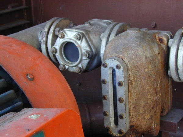
Figure 3: Visual testing method
Temperature Measurement: Sensing upstream and downstream temperatures with contact pyrometers or infrared detectors. This method will determine whether there is blockage (steam trap is cold) as well as providing an estimated operating pressure with a correlation of the temperature to steam pressure.
Ultrasonic Detection: Ultrasound devices that detect high-frequency sounds are a simple method of testing steam trap stations and are extremely accurate. Steam traps make distinctive high-frequency noise during proper operation that can be distinctively heard with a high-frequency ultrasonic device.
- Note: All of the above tools require training of the person assigned to do the task.
Figure 4: Ultrasound steam station testing
9. Conduct an in-depth study and testing of the existing steam trap station: Establish the benchmarks
Add all components, including steam traps, isolation valves, let down stations, etc., to a database. Steam profiling or a steam balance is typically added into the program to understand the dynamics of steam and condensate system.
10. Review the benchmark data
Analyzing the results from Step 10 and then set a road map for correction. The review of the data from the steam trap station study is to define the unreliable components and deficient installations. The goal of the process is to obtain a 3% failure rate in the steam trap station population.
The data results will provide the necessary information on the steam trap stations that are resulting in the highest energy losses, therefore setting the correction roadmap.
All failed steam trap station components will be collected and proceed into the root cause analysis (RCA) process.
11. Root cause analysis (RCA)
RCA is a method of problem solving aimed at identifying the root causes of problems or events that cause the steam trap station components to fail. The practice of RCA is predicated on the belief that problems in the steam system are best solved by attempting to address, correct, or eliminate root causes, as opposed to merely addressing the problem by changing out the component with the same or a similar component. The result of the latter action is that the failure will occur again.
By directing corrective measures for the RCA, it is more probable that failure recurrence will be prevented. However, it is recognized that complete prevention of the failure by one corrective action is not always possible. Conversely, several effective corrective measures (methods) may address the root cause of a problem. Thus, RCA is often considered an iterative process and is frequently viewed as a tool of continuous improvement.
RCA is one the most important keys to a successful steam trap management program.
Figure 5: RCA- enlarged discharged passage due to the steam trap failure and blowing steam
12. Evaluation area
Based on the RCA, there is a possibility to evaluate steam trap station vendors to meet the plant requirements. The team leader should find or locate 6 to 10 steam trap stations that will be used for evaluation purposes. Select a location where it is easy to monitor the steam trap stations’ performance.
Figure 6: Steam trap station evaluation – two visual indicators
Here are some suggestions to follow during the steam trap station evaluation process:
- Ensure the use of the Universal mount design steam traps (ease of change out: 5 minutes or less).
- A test valve arrangement should be used to inspect the steam trap discharge (steam, condensate, flash, etc.) during the evaluation process.
- A video record of proper steam trap operation should be taken for evaluation, benchmarking, and training purposes.
- Select the operational design of the steam traps.
- Set a standard for the operational design of the steam trap that will be used in the different applications found in your plant.
For example: mechanical, thermodynamic, and thermostatic. If you need assistance, please contact one of our SEA field engineers. Most plants need to have more than one operational steam trap design, but not more than two. - Proper steam trap sizing is the most important factor in obtaining efficient steam trap operation. Even though the correct operating design of a steam trap was selected and the installation was correct, improper steam trap sizing will cause either condensate to back up in the system or excessive steam loss into the return system. Be sure to review the necessary considerations in sizing steam control valves, steam piping, expansion, and heat transfer. It is important to take time to consider all the parameters and to evaluate the dynamics of the system while making the correct sizing and selection of the steam trap. Steam trap sizing is not just a selection based upon pipe size. Rather, it is the sizing of the internal diameter of the steam trap discharge orifice. For low-pressure heating systems, commercial steam trap manufacturers have developed steam traps whose pipe size relates directly to the steam trap capacity (orifice size). However, in industrial steam traps, this is not typically the case.
Figure 7: Steam Trap Station Installation wit universal connector and ball valves
A 2” steam trap can have the same capacity as a steam trap with ½” connections. Only following the determination of the condensate capacity, maximum orifice pressure rating, operating steam pressure, pressure differential, and steam trap model have been determined, the pipe size or connections can be selected.
Example:
- Steam line drip leg, unit heater, tracer, or other small condensate loads will use a thermostatic design steam trap.
- Process applications (heat exchanger, reboiler, reactor, etc.) will use a free float: float and thermostatic design steam trap.
- Select manufacturers for the evaluation process.
- The plant needs to evaluate the steam trap station components that will be used in the plant. The best practice is to implement a methodical selection process for steam trap station evaluation and selection of vendors. Even if the plant is using a specific manufacturer, there is a need to reevaluate. New steam traps will leak steam; the plant must select one or two manufacturers with the least amount of leakage.
13. Update the established standards for steam trap station installation
After RCA, the plant may need to update the steam trap installation and connection standards at the plant to reduce the failure rate of steam trap stations in the plant. A high percentage of steam trap failures are due to an incorrect steam trap installation.
14. Where do we get standards?
The Swagelok Energy Advisors, Inc. web site has standard installation prints, which can be provided in AutoCAD format upon request. Standards allow the plant personnel to better understand the operation of each steam trap station and proper installation techniques. This will eliminate repair or replacement costs due to incorrect installation.
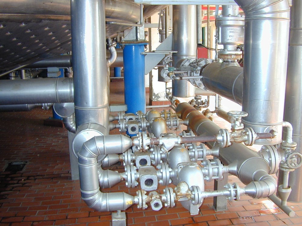
Figure 8: Steam Trap Stations Components
15. Take all benchmark data (after the corrections) and continue the steam trap station program on a PM schedule
Do not let the program stop; the program must continue indefinitely.
- Recommended time schedule for testing steam traps:
i. Process steam traps Every 3 months
ii. High-pressure steam traps Every 6 months
iii. Low- to medium-pressure steam traps Every 6 months
iv. Building heating steam traps Twice a heating season
Conclusion
With today’s rising fuel costs increasing the cost to produce steam, now is a good time to begin a proactive steam trap station program. Do not let the steam system manage you; instead, be the manager of the steam system

