Steam Line Design and Sizing – Best Practice No. 10
Do you want this article in PDF format? Download it here:
Download a PDFBEST PRACTICE NO. 10
HOW TO CORRECTLY SIZE A STEAM LINE
Selecting the correct size for a steam line is one of the most important items in a properly operating steam system. Steam lines are designed for 200 years of operation, and the plant should not experience premature failure with a properly designed and operated steam line.
ne important factor to remember about steam system design is that a steam system must be viewed as a complete system rather than its component parts; therefore, all aspects need to be reviewed to ensure proper operation. For example, undersized steam lines will lead to steam starvation and steam pressure loss at the steam end user. This pressure loss is often mistakenly assumed to result from heat transfer problems or control valve issues.

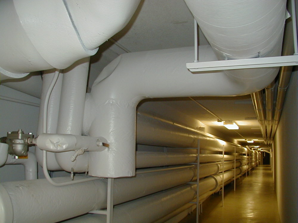
Figure 1: Steam Line Profiling doe Pressure Drops
Providing the correct steam pressure and steam quality to the end user is the goal of the steam distribution lines. Steam lines always will have a steam pressure drop with all the restrictions to steam flow, such as valves, elbows, pipe internal roughness, flow meters, expansion devices, and other items. The plant needs to determine the acceptable steam pressure drop for the steam distribution system and deliver the correct steam pressure to the end user.
When designing steam headers, branch lines, and condensate lines, there are general rules regarding velocities in the piping. Oversizing a steam or condensate line is never a problem except for the additional cost at installation, and it will add a very small additional energy loss through the insulation. However, the benefits of oversizing far outweigh the negatives of undersizing.

Figure 2 Stream Distribution Systems
Undersizing Steam Line Negatives
Undersizing steam lines will increase the steam velocities, which, in turn, will increase the noise (dBA level) and pressure drops in the steam system. Higher velocities of 10,000 fpm or more will present four additional problems in the system:
- Steam quality: High velocities in the steam line will entrain the condensate that forms from thermal losses through the insulation. The end result will be lower steam quality. The design of the steam distribution system should provide at least steam quality of at least 98% to the end user.
- Higher steam line pressure drops: The steam line pressure drops will increase with higher steam line velocities.
- Premature steam line component failures: Poor steam quality in the steam line will cause erosion in the steam line elbows, flow meters, isolation valves, and other items.
- Water hammer: In severe cases, the result could be water hammer in the system.
What Are the Correct Velocities?
- Steam heating system velocities: 6,000 feet per minute
- Process steam velocities: 10,000 feet per minute
- Condensate piping velocities (two-phase flow/flash steam): 4,500 feet per minute
- Condensate piping velocities (liquid only): 420 feet per minute
Sizing Steam Lines for Velocity
Formula for velocity in steam piping:
Velocity = 2.4 x flow x specific volume
cross-sectional area
- Flow = lbs. per hour
- Specific volume (typically at the end of the steam line) cubic ft. per lb.
- Cross-sectional area of the pipe
- Internal area in square inches
Example:
Steam Flow: 110,000 lbs.hr
Steam Pressure: 215 psig
10” Sch. 40 pipe: 78.9 (cross-sectional area)
2.4 x 110,000 x 2.002 = 6,698 FPM
78.9 (Area)
3. Calculating the Steam Line Pressure Drop
When calculating the pressure drop for steam lines of any length, it is not sufficient to depend upon calculations based on velocity alone. Velocity is only one part of the solution.
Formula:
Pd = P1 – P2 = 0.0484 f l G2
D5 W
Pd = Pressure drop in lbs. per square in.
P1 = Initial pressure in lbs. per square in. absolute
P2 = Final pressure in lbs. per square in. absolute
f = Friction factor
G = Lbs. of steam per minute
D = Internal diameter (inches)
L = Length of pipe
W = 1 = weight of steam per cubic feet at pressure P1
Vs
Example:
P1 = 234 psia
Steam flow = 90,000 lbs. per hour
Pipe size = 10”
Pipe schedule = 40
Length = 1,000 ft.
Step 1: W = 1 = weight of steam per cubic feet at pressure P1
Vs
Vs = 1.960 ft.3/lb. , W= 1 = 0.509 lbs./ft.3
1.96
Pressure drop = (0.0484) (0.0053) (1,000) (90,000/60 steam flow mins.)2 (10.02)5 (0.509 lbs./ft.3)
Pressure drop = 234 psig – P2 = 577,170
51,411
Pressure drop = 234 psia – P2 = 11.23
P2 = 222.8 psia
Steam systems typically use a gate valve for isolation, and the design of a gate valve requires equal or close to equal pressure on both sides of the internal gate for the valve to open without external force. If the pressure is not equalized, then an external force, such as a pipe wrench or a cheater bar (the nickname for devices that open gate valves), must be used to open the valve handle. See Figure 1. Using this type of force on a gate valve is an unsafe practice that can lead to injury or death.
As shown in Figure 2, a gate valve will have a force on the P1 (inlet) side that will put extreme force on the gate, thrusting it into the valve seating surface. Using a warm-up valve, the P2 (outlet) pressure will counter the P1 force, and the gate will be allowed to rise without using external forces.
If the plant operation is using a butterfly or ball valve, which are quarter-turn valves, for steam isolation applications, then warm-up valves are essential to bring the system up to pressure. It is impossible to warm up a steam system slowly with the use of a butterfly valve or ball valve that is 3” or larger.

Figure 2: Using a Warm-up Valve with a Gate Value
4. What Size Steam Line Requires a Warm-Up Valve?
When installing an isolation, shutoff, or bypass valve on the steam distribution system (3” or larger), it is necessary to install a small valve (½”, ¾”, or 1”) around the isolation valve. What size the warm-up valve should be depends on the length and diameter of the steam line that needs to be warmed up.
5. Requirements for WARM-UP Valves
All warm-up valves should be selected for the following characteristics:
- The needle valve design is preferred for throttling steam.
- The globe valve is the second choice for internal valve design.
- The internal permissible leak rate standard should be higher than a Class IV shutoff.
- American National Standards Institute (ANSI) or FCI standards
- API standards
- The outlet piping or tubing needs to be increased by one pipe diameter.
- Example: With ¾” inlet piping and a ¾” warm-up valve, the outlet piping/tubing should be 1” or larger. This will reduce the velocities out of the valve and improve the valve’s reliability.
Two valves should be installed on the warm-up line:
- one valve for the warm-up operation, and
- a second valve for isolation.
a. Double block valve with a bleed valve
b. More than one warm-up valve can be installed
c. For larger steam systems
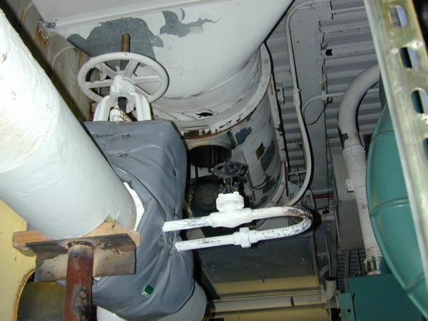
Figure 3. Isolation Valve With a Warm-Up Loop
6. Applications for Warm-Up Valves
6.1 Steam Isolation Valves
One of the most common applications is the steam line isolation valve installation.

Figure 4. Diagram of Warm-Up Valve Installation
6.2 Single-Stage PRV Stations
The single-stage pressure-reducing valve (PRV) is another application for warm-up valves.

Figure 5. Single-Stage PRV
6.3 Two-Stage PRV Stations
The two-stage PRV is an additional application for warm-up valves.

Figure 6. Two-Stage PRV


