Steam System Insulation
Do you want this article in PDF format? Download it here:
Download a PDF1. DEFINITION OF AND PURPOSE OF INSULATION
Insulation is defined as materials or a combination of materials that retards the transfer of heat energy to achieve one or more of the following functions:
- Conserve energy by reducing heat loss or gain
- Control surface temperature for personnel protection, safety, and comfort
- Facilitate temperature control of a process
- Increase operating efficiency of heating, ventilating, and cooling
- Prevent or reduce damage to equipment from exposure to fire or corrosive atmospheres
- Protect the environment by conserving energy while reducing the amount of fuel used for combustion purposes, resulting in lowering emissions
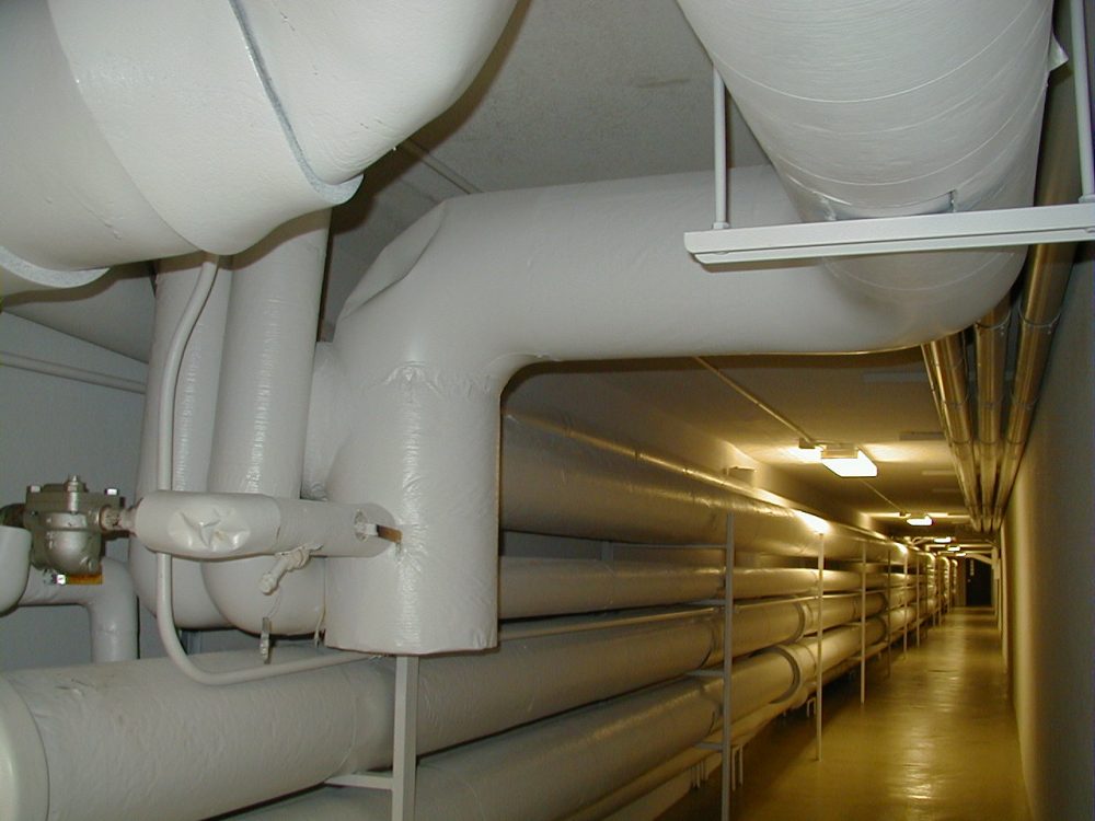
Insulation is the most overlooked item that provides energy savings. According to the U.S. Department of Energy (DOE) Best Practices Steam Program, mechanical insulation should be used on any surface over 120°F (49°C). Typical surfaces to be insulated include boiler surfaces, steam distribution mains, condensate return pipes, vessels, and hardware fittings. Figure 1 shows insulated pipe, while Figure 2 shows uninsulated pipe.
Figures 3 and 4 show how insulation can retard heat loss.
There are two general temperature ranges for insulation application for steam and condensate systems:
1.1. Intermediate Temperatures
- 61°F (16°C) through 211°F (99.4°C) for condensate
- 212°F (100°C) through 600°F (315.5°C) for steam and high temperature condensate
1.2. High Temperatures
- 601°F (316°C) through 1500°F (815.5°C) for turbines, breechings, stacks, and boilers
2. FORMS OF INSULATION
Insulation is available in a variety of forms suitable for specific functions and applications.
Some of the most widely used forms are rigid, cement, and flexible forms.
2.1. Rigid Forms
- Rigid forms include boards, blocks, and sheets
- Preformed shapes are produced from cellular, granular, and fibrous insulation
2.2. Cement Forms
- Cement (insulating and finishing) forms are produced from fibrous or granular insulation combined with cement.
- These forms are used to fill in irregular surfaces that cannot be insulated using pipe or block insulating products.
2.3. Flexible Forms
- Flexible forms are cellular and fibrous insulation produced in flexible sheets.
- Fibrous insulation is used to produce flexible blankets and contoured envelopes for enclosing valves and other irregularly shaped items.
- Poured or froth foam is used to fill irregular areas or voids. Foam spray is used for flat surfaces.
- Spaces or voids around oddly shaped items are sometimes filled with loose granular or fibrous insulation.
3. INSULATION COMPOSITION
3.1. Fibrous Insulation
Fibrous insulation is composed of small diameter fibers that finely divide the air space to create the insulating space. The fibers may be perpendicular or horizontal to the surface being insulated, and they may or may not be bonded together. Some examples of fibrous insulation are silica, rock wool, slag wool, and alumna silica fibers. However, the most widely used types of this insulation are glass fiber and mineral wool.
3.2. Cellular Insulation
Cellular insulation is composed of small individual cells separated from each other. The cellular material may be glass or foamed plastic, such as polystyrene (closed cell), polyurethane, and elastomeric.
3.3. Granular Insulation
Granular insulation is composed of small nodules that contain voids or hollow spaces. It is not considered a true cellular material since gases can be transferred between the individual spaces. This type of insulation may be produced as a loose or pourable material or combined with a binder and fibers to make a rigid insulation. Examples of this type of insulation are calcium silicate, perlite, and expanded polystyrene.
All of the above materials use air as the primary insulator. The air spaces between materials retard the heat transfer within the material due to the low heat transfer coefficient of air.
4. INSULATION VALUE
Comparing the effectiveness of different insulation is done by using the K-value. The K-value (thermal conductivity) is the measurement of how much thermal energy will pass through a fixed area of a material. The lower the K-value, the higher the insulation value. K-values vary with different service temperatures. Occasionally, a U-value is used in evaluating insulation. The U-value (thermal transmittance) is simply the K-value divided by the material’s thickness.
Units for K-values are expressed in Btu•in/h•ft²•°F for imperial units and W/m•°C for SI units. Units for the U-value are expressed in Btu/h•ft²•°F for imperial units and W/m2•°C for SI units.
5. INSULATION MATERIAL PROPERTY COMPARISON
5.1. Calcium Silicate
Calcium silicate is a granular insulation that is reinforced with fibers and molded into rigid forms.
- K-value: 0.38 Btu•in/h•ft²•°F
- Service temperature up to 1200°F (649°C)
- Flexural strength is good
- Water absorbent but material can be dried out without deterioration
- Non-combustible
- Primary use on hot piping and surfaces
- Jacketing is to be applied in the field
- ASTM C 533
5.2. Glass
Insulation made of glass is available with a fibrous or cellular structure.
5.2.1. Fibrous Insulation
- K-value: 0.22 Btu•in/h•ft²•°F
- Available in pipe, flexible blanket, or rigid board
- Its
- Service temperature up to 1000°F (538°C); it is most commonly used in temperatures up to 450°F (232°C)
- In rigid form, the bonding material determines the temperature limit
- Chemically neutral and noncombustible
- ASTM C 547
5.2.2. Cellular Insulation
- K-value: 0.33 Btu•in/h•ft²•°F
- Can be rigid board, block, or various shapes
- Service temperature up to 900°F (482°C)
- Good structural strength, poor impact resistance
- Material is non-absorptive and resistant to most chemicals
- Noncombustible
- ASTM C 552
5.3. Mineral Fiber
This insulation is composed of rock, glass, or slag fibers that are bonded together with a heat-resistant binder. It is used in loose form, bonded shapes, and or pipe insulation.
- K factor: 0.48 Btu•in/h•ft²•°F
- Service temperature up to 1200°F (649oC)
- Chemically neutral
- Rigid cellular structure reinforced with fibers and binders to resist moisture penetration
- Noncombustible
- ASTM C 547
5.4. Plastic Foam
Plastic foam insulation is a rigid, closed-cellular material. Its chemical content varies by manufacturer.
- K factor: From 0.18 to 0.28 Btu•in/h•ft²•°F
- Cellular molded with fiber into rigid forms
- Service temperature up to 250°F (121°C)
- Poor structural strength
- Non-absorbent
- Most are combustible
5.5. Refractory Fiber
Refractory fiber insulation is made of mineral or ceramic fibers, including alumina and silica, bound with extremely high temperature binders. A common type supplied in felt form is Cerafelt.
- Service temperature up to 2400°F (1316°C)
- High thermal shock resistance
- Noncombustible
- Insulating cement
5.6. Cement
- Moderate insulation value
- Mixed with fibers, binders, and water
- For irregular surfaces
- Requires reinforcement because it is shrinkable
- Intermediate temperature to 600°F (316°C)
- Noncombustible
6. COMPARISON CHART OF TYPICAL INSULATION MATERIAL
- Insulation Type Temperature Rating K-v Value (Btu•in/h•ft²•°F)
- Calcium Silicate 1200°F (649°C) 0.38
- Glass: Fibrous and Cellular 1000°F (538°C) 0.22 to 0.33
- Mineral Fiber 1200°F (649°C) 0.48
- Perlite 1200°F (649°C) 0.55 to 0.80
- Plastic Foam 250°F (121°C) 0.18 to 0.28
- Refractory Fiber 2400°F (1316°C) N/A
- Cements 600°F (316°C) N/A
These temperatures depend on the insulation rating type per the ASTM specifications and manufacturer.
7. PROTECTIVE COVERINGS AND FINISHES (LAGGING)
The efficiency and service of insulation depend directly on its protection from moisture entry and mechanical or chemical damage. Choices of jacketing and finish materials are based upon the mechanical, chemical, thermal, and moisture conditions of the installation. Certainly, cost and appearance requirements are additional variables in the choice. At a minimum, labels should be applied to the outside of the lagging identifying the contents and flow direction.
7.1. Considerations for Protective Coverings and Finishes
7.1.1. Internal Mechanical Forces
Expansion and contraction of the pipe or vessel must be considered because the resulting forces are transferred to the external surface of the protective covering.
7.1.2. External Mechanical Forces
If a pipe, vessel, or a specific area is subject to mechanical abuse (e.g., tools being dropped, abrasion from wind-driven sand, or personnel walking on the system), then these need to be considered in the design. These considerations may affect the insulation type used as well as the weather barrier jacket type.
7.1.3. Chemical Resistance
Some industrial environments may have airborne or spilled corrosive materials that accumulate on the weather barrier and can cause a chemical attack of the pipe or vessel jacketing that was selected.
7.1.4. Galvanic Corrosion
Different metals can react with each other and form a corrosive environment under certain conditions. This should be considered between the pipe and vessel material as well as the metal jacket being selected.
7.2. Types of Coverings
Coverings are classified into six functional types.
7.2.1. Weather Barriers
The basic function of the weather barrier is to prevent entry of water, ice, or snow into the insulation. Jacketing may be metal or plastic and must be overlapped sufficiently to shed water. Commonly used materials and thicknesses for protection are as follows:
Material Indoors Outdoors
- Bare aluminum 0.016” (0.406 mm) 0.024” (0.610 mm)
- Coated aluminum 0.016” (0.406 mm) 0.024” (0.610 mm)
- Stainless steel 0.010” (0.254 mm) 0.016” (0.406 mm)
- PVC 20 mils 30 mils
Aluminum is weather resistant but susceptible to corrosive chemicals. Coated aluminum can be used to provide additional corrosion protection and to provide higher values of surface emission where needed. Stainless steel offers the best chemical resistance and is offered in types 304 and 316. Type 316 offers greater chemical resistance than type 304.
PVC jacketing is typically field applied over unfaced insulation where additional protection is necessary. PVC jackets are available in several thicknesses and colors. The most common thicknesses are 20 and 30 mils, with 30 mils recommended for outdoor applications. Jacketing temperatures should be kept below 150°F (66°C). Outside use should be ultraviolet resistant.
7.2.2. Vapor Retarders
Vapor retarders are designed to retard the passage of moisture vapor from the atmosphere to the insulated surface. Joints and overlaps must be sealed with a vapor-tight adhesive or sealer free of pinholes or cracks. Forms of vapor retarders include the following:
- Rigid jacketing: Plastic fabricated to the exact dimensions and sealed vapor tight.
- Laminated foil jacketing: Laminated foils and treated or coated products that are field or factory applied to the insulation material. Various forms exist:
- ASJ: All service jacket with self-sealing lap consists of white kraft paper bonded to aluminum foil and reinforced with glass fibers
- FSK: Foil scrim kraft consists of aluminum foil and fiberglass-reinforced scrim with a kraft backing
- Mastic coating: Mastic provides a seamless coating. This coating is most often applied by brush or trowel or sprayed in coats at the manufacturer’s recommended application rate with a reinforcing mesh embedded between the first few coats. Typical reinforcing meshes are made of synthetic fibers, fiberglass scrim, or cloth and canvas cloth.
- Flexible membranes: Flexible jacketing/cladding may be single or multiple-ply combinations of materials and are often supplied with a self-adhering system.
7.2.3. Mechanical Abuse Coverings
Rigid jacketing provides the strongest protection against mechanical abuse from personnel, equipment, and machinery. The compressive strength of the insulation material should be considered when designing for mechanical protection. Insulated piping within reach or under foot will be abused. Areas with the most abuse should be supported from within to prevent compression. Heavy metal lagging will protect against abrasive wear.
7.2.4. Corrosion and Fire Resistant Coverings
Corrosion protection can be applied to the insulation by using various jacket materials. The corrosive atmosphere must be determined to properly select compatible material. Mastics may be used in atmospheres where jacketed materials would be damaged.
Insulation systems may be made fire resistant by using certain jacketing and/or mastics. Materials are determined to be fire resistant if they inhibit flame spread, reduce smoke generation, and are not an additional fuel source. The total system should be considered when designing for fire resistance.
ASTM E 84, 25/50 Flame/Smoke ratings: Tested in a 25 foot (7.62 meters) tunnel upside down. A flame is ignited, and a fan blows at a rate of 240 feet (73.15 meters) per minute. Flame propagation and the quantity of smoke released are measured.
7.2.5. Hygienic Coverings
To be considered hygienic, coatings and jackets must present a smooth surface that resists fungal or bacterial growth in food processing areas. High temperature steam or high-pressure water wash down conditions require jackets with high mechanical strength and temperature ranges.
7.2.6. Appearance Coverings and Finishes
Various coatings, finishing cements, fitting covers, and jackets are chosen primarily for their appearance value in exposed public areas.
8. ACCESSORIES
The term accessories refers to devices or materials serving one or more of the following functions:
- Securements
- Reinforcement for cement or mastic applications
- Supports
- Sealing and caulking
- Flashing
- Expansion/contraction compensation
8.1. Securements
Most insulation is not structural in nature and must be supported, secured, fastened, or bonded in place. Possible choices to enhance the structural nature of the insulation include the following:
- Studs and pins
- Rivets and screws
- Clips
- Wire or staples
- Self-sealing laps
- Tape*
- Adhesives*
*Ambient temperature and humidity affect tapes and adhesives. It is usually best to use a mechanical securing system wherever possible.
8.2. Reinforcement for Cements and Mastics
Fiber fabrics, expanded metal lath, or metal mesh can be embedded in the cement to add strength.
- Stiffening: Metal lath can be applied on surfaces before heavy density insulation is applied. Three types of metal lath most commonly used are the following:
- Diamond mesh
- Expanded rib
- Woven wire
8.3. Supports
Insulation support rings on vertical piping and vessels should be provided by the piping or vessel contractor. It is not acceptable or recommended to weld in the field on an ASME code-stamped vessel for insulation purposes. Field welding on coded piping or vessels voids the original coding by the manufacturer.
8.4. Sealing and Caulking
A variety of sealers and caulking are available for sealing vapor and weather-barrier jackets and joints. These products are manufactured in a large range of temperature and vapor permeability properties. Some are designed specifically for use with one type of insulation or manufacturer’s products.
8.5. Flashing
Material that directs the flow of liquids away from the insulation. Flashing can be made from metal, plastic, or mastic.
8.6. Expansion/Contraction Compensation
Accessories used in the design of expansion/contraction joints include the following:
- Manufactured overlapping or slip joints
- Bedding compounds and flexible sealers
Improper design or application of one or more of these accessories is a significant factor in the failure of insulation systems.
9. INSULATING AUXILIARIES
- Valves: Removable forms
- Flanges: Cuff/removable
- Expansion joints: Sliding
- Traps: Depends on type
- Boilers: Typically no additional insulation needed
- Turbines: Removable forms
- Safety valves: Per manufacturer’s recommendations
9.1. Valves
Steam valves should be insulated. Insulating conserves energy and also provides personnel safety protection. Since valves require periodic maintenance, the form of insulation used on valves should be easily removable and replaceable. Many manufacturers provide custom-made insulation jackets that fit their valves. These are usually very snug fitting without voids and are very efficient.
Blankets or loose-fitting envelopes many times leave voids that should be filled with a pourable material to maintain efficiency. In heat loss calculations, an uninsulated valve is estimated as one linear foot of bare pipe equal to the nominal valve size.
9.2. Flanges
Flanges should also be insulated both for personnel protection and energy conservation. Most flanges can be insulated the same as the pipe unless the flange is periodically opened. When frequent inspection or dismantling is required, a removable and reusable covering should be used.
9.3. Steam Traps
There has been a lot of confusion regarding insulation of steam traps. Steam traps do require periodic maintenance, which will require the removal of insulation. Periodic replacement of insulation may outweigh the savings in heat loss. Removable/reusable forms are best suited for steam trap insulation. In many cases, steam traps are insulated for personnel protection. Insulated steam traps are sometimes hidden or installed improperly to be out of reach. The operation of steam traps is affected by insulation and some types should not be insulated. Please refer to the steam trap manufacturer’s guide for insulation recommendations.
9.3.1. Float and Thermostatic Steam Traps
- Large surface area
- Insulation has no effect on operation
- Use removable form
9.3.2. Inverted Bucket Steam Traps
- Large surface area
- Do not insulate
9.3.3. Thermodynamic Steam Traps
- Do not insulate
- Should be shielded against rain/snow conditions on top of the bonnet
9.3.4. Thermostatic Subcool Steam Traps
- Do not insulate
- Insulation will cause a backup of condensate in the system. These steam traps require a certain amount of temperature differential in the condensate leg to function correctly.
- Shield for safety
9.4. Heat Exchangers
When possible, all heat exchangers should be insulated. Both fixed insulation and removable types are appropriate. If periodic cleaning disassembly is required, removable forms are preferred. If the heat exchanger is code stamped, it is important that the nameplate be raised to the height of the insulation so that it is visible.
9.5. Boilers
Typically, there is no need to add additional insulation over that provided by the manufacturer. However, it is important to seal any openings in the jacket, particularly on the top, to prevent moisture from entering and wetting the insulation.
10. UNDERGROUND INSULATION
When working with underground insulation, the following conditions should be considered:
- Soil make-up, which would include water table, type of soil, drainage, corrosive elements, electrical currents, the soil’s permeability, and shoring if required
- Temperature range/expansion and contraction
- Type of system to be insulated, such as:
- Steam and condensate piping
- Heating hot water piping
- Chilled water piping
- Process piping
- Domestic hot water piping
- Fuel oil piping
- Underground storage tanks
10.1. Box Trench or Tunnel
- Insulated pipes are encased by trench or tunnel. See Figure 16.
10.2. Direct Burial
- Insulation and jacketing are chosen with properties necessary to resist damage from various soil conditions.
- Density, strength, and water absorbency would apply and must be considered.
- Special consideration should be given to waterproofing the insulation. See Figure 17.
10.3. Pour in Place
Several pour-in-place insulation products are on the market presently. With slight variations, they are all installed in a similar manner. Check manufacturers’ recommendations for exact dimensions represented in Figure 18 as A, B, and C.
11. INSULATION THICKNESS JUSTIFICATION
Determining the proper thickness of insulation according to the insulation’s purpose will justify its cost. To determine the appropriate surface temperature of the outer surface, you need to determine whether the insulation is intended to prevent losses (economic reasons) or whether it is to protect personnel. Service conditions will also affect the required thickness for insulation. Factors such as whether the insulation is indoors, in a covered building with no walls, or subject to outdoor temperatures and wind speed, will all play into the determination of the proper thickness of the insulation.
Many computer programs are available for determining the correct amount of insulation for each application. A considerable amount of information is available for determining the exact thickness and type of insulation required to maximize the payback savings. Any manufacturer will provide justification data upon request.
Insulation thickness guidelines are as follows:
- Pipe size up to 2 in. (50 DN) requires a minimum of 11/2 in. (3.8 cm) of insulation
- Pipe size from 2 in. to 8 in. (50 DN to 200 DN) requires a minimum of 2 in. (5 cm) of insulation
- Pipe size over 8 in. (200 DN) requires a minimum of 31/2 in. (8.8 cm) of insulation


