Steam Safety Valves

My name is Kelly Paffel, Technical Manager for Inveno Engineering, LLC, located in Tampa, Florida. We are an engineering firm focused on steam and condensate systems. Today I want to talk about steam safety valves: sizing, selection, installation, best practices. Steam safety valves installed wherever the maximum allowable working steam pressure of a system or over pressurizing a containing vessel is likely to be exceeded. In particular under fault conditions due to a failure of another piece of equipment in the system.
The typical system we have a pressure inducing valve here. We have a pressure 200 PSI here. And our equipment down here is only rated for 150 PSI, then we need to protect it with a safety relief valve. And typically, that safety relief valve will be set for the lowest rated equipment or component in the system; pressure and temperature rating.
The codes for this steam safety valve is governed by the American Society of Mechanical Engineers (ASME). ASME, through its committees, has established Boiler and Pressure Vessel Codes for safety though rules and formulas indicating a good practice. The National Board of Boiler and Pressure Vessel Inspectors has the authority to verify, administer and enforce this ASME code wherever it has been adopted. Therefore any safety valve that we must follow the code set out by ASME and under the jurisdiction of the national report.
Steam safety valve codes. In the steam system, we look at section one which is for the boilers or power boilers. Section 4 is for heating boilers and section 8 is for pressure vessels out there away from the boiler in the steam system. So, anything away from the boiler, we’re typically looking at section 8, safety valves. The example shows right here, this picture here shows the safety valve located on the boiler, which is going to be section 1.
The code stamps and it’s meaning, we have A, M, N, PP, S, U, U2, UV, and V. So these are the codes and these are the meanings of the code. For example, PP is pressure piping, S is for power boilers, U is for pressure vessels, and V is for boiler safety valves.
We’re going to discuss sizing and selection of a safety valve. We’re looking at the design type. The design type can be the standard safety valve, which is shown here, or we can use pilot operated. Then we have body drains, a lifting device here. Some people prefer to have a lifting device, some people do not prefer. Of course the materials here have to be rated for the max pressure and temperature of the system. So that depends on the material, so if we get in to the higher pressures, when we’re dealing with super heat, then materials have to be selected for that super heat pressure and temperature.
The sealing adjustments typically is adjustments here for the over pressurization in blow down, and the set point tolerance has got to be come up with on safety valves. Now, we’re now getting into the details on the internals of the safety valve and we’re going to talk about the selection process.
So here’s a typical application, we’re going to do this for pressure reduction. So we’re reducing steam pressure here, downstream here. Our equipment downstream, we have a device that only rated for 100PSI, 338 degrees. So we’re going to have to put in a safety valve here. So we’re reducing the pressure here to 50PSI for our operation, but we have to protect the system which is going to be 100PSI chain.
Now, the thing is that we typically have a 10 percent differential between the operating set pressures recommended, and the thing is that this pressure differential would be, if we’re operating at 100PSI, or our safety valve is set for 100PSI and we want to operate at 90PSI or lower. That’s due to, the safety valve can go into, what we call simmer[inaudible 00:05:27] so we want to be at least 10 percent away from our set pressure of our safety valve for the operating pressure of the system. Now, some people recommend 20 percent, and that gets into the lower pressure operation where we’re reducing pressures down to 10 or 12 PSI and we have our safety valve set there for 5PSI. So if my system safety valve is set for 15PSI, it would operate the system at 10PSI to stay away from that simmer effect of the safety valve and that’s per code that the safety valve can go into simmer.
The total capacity of a safety valve at set pressure must exceed the control valve or pressure-reducing valve’s maximum capacity, if the valve were to fail in a fully open position. So if this valve were to fail in the fully open position, this safety valve has to be able to discharge the total capacity. Now, total capacity of the boilers, is the maximum BTU fuel input on the boiler. So the safety valve must be able to relieve the maximum steam output with the maximum BTU input to that boiler, depending on the type of fuel that you’re using for that boiler. Multiple safety valve installation is possible if the capacity can not be reached with one safety valve. It’s common to find that with boilers that we have two or three safety valves to get to the capacity that’s required for that operation.
The steam safety valves sizing designation is designated by numbers. Excuse me. Letters. So up here you’ll see the letters, here. K, L, M, N, P. That gives us the effective orifice area. So if I have a set pressure here 100 PSI, and a P orifice, we have this capacity here, which is around 37012 pounds per hour. So we look up the safety valve and see 4 by 6 P. P means the orifice inside the safety valve.
Now, a safety relief valve must be mounted in the vertical position. The reason mounted in the vertical position is a safety valve is set up as assembled or manufactured in the vertical position, so you must duplicate how the position is of the safety valve. The system must be free of dirt of course. Upstream piping connection must be at least equal to the valve, so if the end of the valve is 6 inches, then this connection valve here needs to be 6 inches.
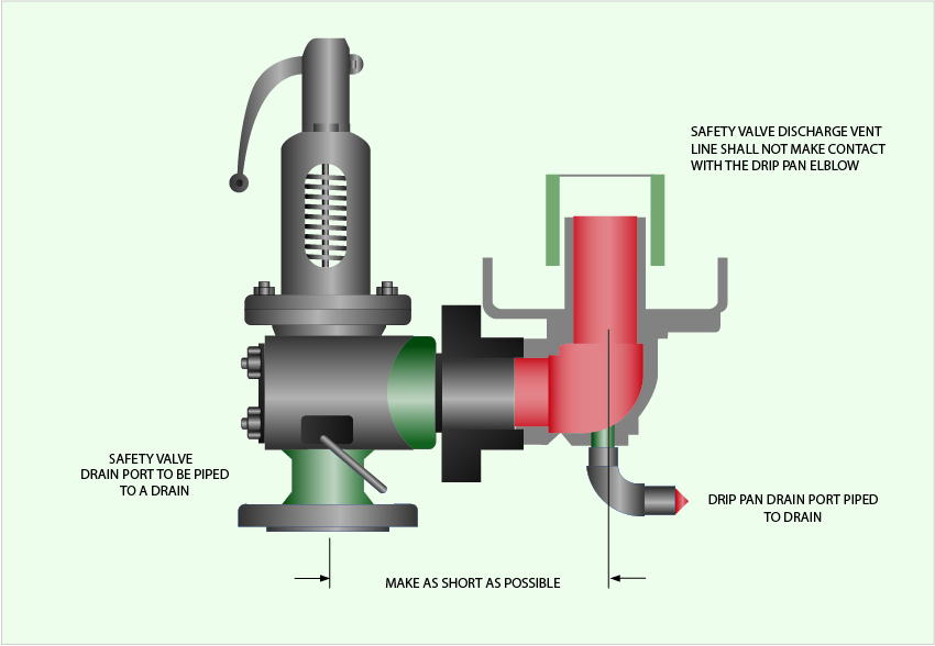
With the steam safety valve no shutoff valve can be installed down here, and do not plug the drain valves, and the discharge lines should be no less than the full area of the valve. In the [inaudible 00:08:38] that make sure we have a drip pan elbow put onto the valve, and this just changes direction from horizontal to vertical, and increases the pipe on pipe diameter, and then the vent pipe can come down but does not make contact with the drip pan elbow. The outlet always must discharge where no one can be at harm’s way, typically to the top of the building or the unit, and cut it at a 45 degree angle to signify it’s a steam safety valve. So you cut it at a 45 degree angle, it used to be 7 feet, and this has recently changed, it’s now 10 feet above. That’s a typical installation of a safety valve.
We also have best practices up on the website, to go into more detail on safety valves, but this is just a short version to give you some idea. So if we can be of service, here is out contact information, and have a great day.


