Steam and Condensate System Waterhammer | Part 2/3: The different types of Waterhammer
Continuing with water hammer in the steam and condensate system segment two, types of water hammer.
We can put water hammer into five major areas, hydraulic shock, thermal shock, flow shock, differential shock, and flooded shock.
Hydraulic shock, a small percentage of water hammer, not too significant, will be hydraulic shock. Like condensate pumps on, off, or condensates or liquid valves turned on too fast. Very, very small percentage.
The major source of water hammer is thermal shock, steam collapses, water is accelerated into the resulting vacuum from all directions with great speed. In a bi-phase condensate system, steam bubbles may be introduced below the level of condensate in the condensate line, or a tank, or condensate tank. An example would be what’s showing here on the right-hand side.
So, the thing is, is the in process P1, right here, we might be supplying 150 psi steam, which is 366 degrees to the process here at P2, which we could reduce the pressure to 100 psi or 338 degrees. So, the condensate would be here coming down to the steam trap. The condensate will be at 338 degrees at P3. We’re going to pass this through a pressure reduction going through a steam trap to our lower pressure which is in the condensate system, P4. How does a condensate get its temperature down to the lower pressure, a percentage is released into flash steam?
The flash steam will be in bubbles, as it carries along up to the condensate line, pressure is reduced, the bubble will increase in size. When the bubble comes in here below the condensate level in a condensate line, the bubble will collapse, and you’ll hear “ping, ping, ping, ping.” Now, if there’s a higher flower of condensate, the bubble will be much larger, and you’ll hear “bang, bang, bang.” So, the thing is that to resolve thermal shock or water hammer, always connect to the top of the condensate header, as showing right here. Even if the condensate line is totally filled with condensate, the flash will dissipate the top of the water, the condensate, without any noise effect.
So, in condensate systems, the connection always must be to the top, never the side or the bottom, and that will resolve the thermal shock or water hammer. Now as showing here on the right-hand side, this is causing water hammer. As you can hear, the “ping, ping,” and the movement into the pipe because it’s connected into the side of the header right here. Solution to this? Very simple. Re-pipe back into the top of the header and the water hammer will go away.
As you see, they went through a variety of steam traps, piping, flex hoses, tried to resolve the water hammer. It’s not going to resolve it. Piping to the top of the condensate header resolves the water hammer. Here’s another video here. This is connected into the bottom of the condensate header, again, the same result. Again, the solution is to come here, pipe into the top of the condensate header, and the water hammer will go away.
Another type of water hammer, this here was a case study where it was piped into the top of the condensate header, but due to the velocities here being so great, the flash was being pushed below the water level and the bubble collapsing. And you can hear the sound of the bubble collapsing. And calculations, the velocities were up around 18,900 feet per minute forcing the flash below the condensate level, causing severe damage to the flanges and the piping surrounding this connection.
Solution? We separated the flash from the condensate line. That reduced the velocity of the condensate or liquid coming back into there, and there was no flash. We got the velocities down to about 3,000 feet per minute and resolved the water hammer issue.
Another water hammer was just from a small steam trap here. And you can see the movement in the pipe, and this is just from one steam trap. You can see, just one steam trap, how much movement this is causing into the piping system. Solution? Just re-pipe to the top, water hammer went away. So, the point is, even one connection can cause this severity of water hammer occurring into the system or the thermal shock water hammer.
Another application, thermal shock or thermal shock water hammer, as you can see the connections up here into the side, up here. And you can hear the pinging noise. Some of the movement that is occurring from the water hammer, so again, solution? Come back here, re-pipe just like this condensate header here to the top of the condensate header and the water hammer went away.
So thermal shock elimination, easy. Always pipe to the condensate lines in the top of the condensate header, then there will be no water hammer. As shown right here, coming back up here into the top and then there’s no water hammer. Even if the condensate line is flooded. So, another picture showing here is connection into the top on a horizontal header coming into the top, process steam traps are here, no sound, no noise effect.
The next type of water hammer is flow show. Steam flowing down a cold pipe at high velocity producing a large quantity of condensate that is traveling at a high velocity. Condensate will continue to build in a mass as it travels along the steam pipe and a large wave of condensate is created. The wave will travel at the same high velocity as a vapor, and sudden change of direction or component to stop the wave, possible elbow, valve or flow meter in the steam line and you’re going to have a severe reaction or flow shock water hammer.
Now, I don’t have any videos of this here and I don’t want to be around when flow shock occurs either, but anyway, isolation valves do not have warm up valves. One of the things when we put in an isolation valve three inch or larger, you always must have a smaller valve, or what’s called a warm up valve. This allows us to warm up the steam system gradually, and thus, we don’t have flow shock to occur. But you cannot go up and try to open an eight-inch valve slowly and try to warm up a steam system. The other thing, a good practice we always do is put a drip pocket ahead of any valve that shuts off. Be a control valve, isolation valve, it just … Here it is. A device or station here, steam trap station or move the condensate. If this valve shuts off, it’s off for a period of eight hours, 10 hours, condensate will build up here in front of the valve. Last thing you want to do is go and open this valve and allow condensate, a slug of condensate to flow into the steam line.
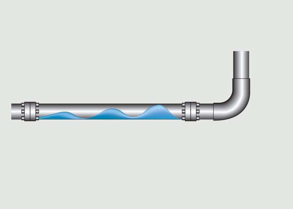
So, two things with flow shock is to always make sure you have a warm up valve around the isolation valve, and it’s a good practice to have a steam trap station ahead of the isolation valve to remove the condensate. Differential shock water hammer. Second largest contributor to water hammer in the system. Steam and condensate will flow in the same, but at different velocity, and this is in the condensate line. Condensate, you have condensate flash steam and blow through steam from failed steam traps, bypass valves, and the condensate line. Remember, we want the condensate lines to be at 4,500 feet per minute.
Now if we would see 4,500 feet per minute in the condensate lines, the velocities are so high that it creates a wave that is shown here, that the wave seals at the top and the bottom, now the wave will have the same speed and it wants to go into a straight direction, and then this elbow wants to stop that wave, and you get a violent reaction. We call that differential shock water hammer.
So, an example of high velocities in a condensate line, just pay attention to this pressure gauge when I play this video. And you will see, bang, see the pressure gauge increased right there. That is that wave coming down that condensate line. As you can see that the supports are damage and about ready to fail, there was flange failures, couple weld failures, and the correction was instituting a correct steam trap management program. There were so many steam traps that were failed and blowing steam in there that caused the high velocity in this condensate line.
Another differential shock video here. You can see the movement, excuse me. You can see the movement of the piping [inaudible 00:12:03] here. Again, the differential shock was caused by undersized condensate line, which produced a high condensate kind of velocity, and you can see the reactions that were occurring in the system. What ended up in this application was a new condensate line had to be installed, properly sized, supported, and guided into the system.
So, this is just a little bit better close-up … Excuse me, I’m sorry. This is just a little bit better close-up of the previous … And you can see the damage to the support, the effects of water hammer. Extremely unsafe condition due to plant personnel being in this vicinity where this condensate line. So, the correction happened immediately.
Here’s another video of another condensate line, and again, this is undersized condensate line produced a high velocity. As you can see, there is one connection right here into the bottom of the condensate header. The correction, we removed the flash steam from the condensate line and re-piped the connection to the top of the header and the water hammer went away.
Flooded shock water hammer is caused by undersized steam traps, and the thing with undersized steam traps, as I said in the previous segment or segment one, and the sizing up the drain device here, you must take time and effort to understand P3, P4, or the differential pressure across the orifice and the steam trap. One of the key factors is understanding what is P4, and that’s based on the dynamics, or P5, or the condensate header. So, if the steam trap is not undersized correctly, condensate’s going to back up. Get condensate into heat transfer, it’s not designed for condensate or what we call flooded conditions, and you’ll get waves occurring inside the heat exchanger due to the configurations of heat exchangers, and you’ll get water hammer.
And it will cause tube failure or tube sheet failure, [inaudible 00:14:42] failure, support failure inside the heat transfer, pipe and frames, gasket failure, gasket material failure, just causes a lot of issues, so the thing with sizing steam traps, take the time to understand what the differential pressures are, P3, P4. Always have a qualified vendor supporting you on the sizing application and know the dynamics of your condensate return system. That resolves a lot of the issues with what we call flooded conditions. The thing is, the steam trap station, you always want to make sure that you’re sized for the lowest differential across a steam trap, and there’s a sizing factor that goes into steam trap sizing, so to understand the sizing factor, apply it correctly. Again, have a qualified vendor support you in your efforts of sizing your steam traps correctly.
And this will conclude segment two, and this is just a little bit on our company, our approach. We are your partner and you can contact myself or Graham anytime or email is right here to help you resolve and prevent water hammer in your system, so thank you.


