No. 67 Properly Size A Steam Trap

Correctly Sizing Steam Trap Stations
BEST PRACTICE NO. 67
HOW TO PROPERLY SIZE A STEAM TRAP
READ FULL PDF TECHNICAL PAPER – CLICK HERE
1. STEAM TRAP STATION SIZING
Proper steam trap sizing is the most important factor in obtaining an efficient and reliable steam trap operation. Even if the correct operational design of the steam trap is selected and installed perfectly, incorrect steam trap sizing will cause either condensate backup or steam loss.
Steam trap sizing does not mean selecting the steam trap connection size; rather, it refers to the proper sizing of the internal condensate discharge orifice. For low steam pressure heating systems, steam trap manufacturers produce steam traps with a steam trap connection size that relates directly to the steam trap capacity (orifice size). However, industrial steam trap sizing requires properly sizing the steam trap discharge orifice. A 2” piping connection on the steam trap can have the same condensate capacity as a steam trap with a ½” pipe connection. After determining the condensate capacity and internal condensate discharge orifice size, then select the steam trap pipe connection size to meet the installation requirements.
** Note: Steam trap connection size is a convenience for the installation process. It has no effect on condensate capacity.
2. DATA NECESSARY TO SIZE A STEAM TRAP STATION
To determine the correct steam trap orifice size, the following data is required:
- Determine the maximum pressure on the steam line supplying the process. The steam trap design and materials have to be rated for the maximum steam pressure and temperature.
- Maximum steam pressure (steam trap body rating)
- Maximum steam temperature (steam trap body rating)
- Select the steam trap orifice, which must be rated for the maximum steam pressure used in the process. The maximum pressure is especially critical in mechanical steam traps.
- The maximum pressure is determined by the safety valve set pressure that is protecting the steam system or process.
- Determine the inlet pressure to the control valve.
- Document the steam pressure at the steam control valve inlet. Do not assume the steam line operating pressure will equal the steam pressure at the control valve. Pressure drops in the steam line have to be considered.
- Determine the outlet pressure from the control valve to the process.
- There is a calculated pressure drop across the control valve. This information can be determined from the steam control valve performance information.
- Calculate the pressure drop (heat exchanger).
- All heat transfer components have a pressure drop. This information can be obtained from the heat transfer performance sheets.
- Calculate the inlet pressure to the steam trap.
- Subtract the heat transfer pressure drop from the steam control valve outlet pressure to determine the inlet pressure to the steam trap station.
- Determine the outlet pressure at the discharge of the steam trap.
- Calculate the condensate flow rate.
- Maximum condensate capacity (lbs./hour)
- Minimum condensate capacity (lbs./hour)
- Choose the sizing factor depending on the steam trap design.
- Determine the steam trap discharge pressure or the condensate return line pressure.
- Calculate the minimum differential pressure across the steam trap (ΔP) (inlet pressure – outlet pressure).
- Evaluate the condensate flow condition in the steam trap operation.
- On/off condensate flow
- Continuous flow operation
The maximum steam pressure is easily determined by either the design specification of the system or by the set pressure of the safety valve that is protecting the steam system. Operating steam pressure can be obtained from a pressure gauge in the system.
The condensate capacity requirements are sometimes more difficult to obtain. Condensate capacities may be shown either in design specifications or on equipment nameplates. If the condensate capacity is not shown, it will be necessary to calculate the condensate capacity by using heat transfer formulas. One basic item to remember is that one pound of steam condenses to one pound of liquid or condensate. If pounds/hour of steam is known, the condensate capacity is the same. If equipment is rated in BTU/hour, the capacity in pounds/hour can be approximated by dividing by the latent energy of the steam pressure at the equipment.
Another helpful factor is the steam control valve supplying the process. If a steam control valve can flow (x) pounds per hour of steam, then the steam trap must be able to flow the same amount of condensate.
3. BACKPRESSURE: STEAM TRAP STATION CAPACITY
A high percentage of steam trap applications will have pressure at the discharge side of the steam trap from the condensate return system. The backpressure may be unintentional or deliberately produced by the design or by the operation of the condensate return system.
3.1.Unintentional Backpressure
Unintentional pressure is caused by a static pressure or rise in condensate piping after the steam trap. The main condensate lines are typically installed at a high elevation and located above the steam traps; therefore, it is necessary to pipe the condensate from the steam trap location up to the higher condensate mains. A rule of thumb is that every foot of rise in the condensate line after the steam trap equals ½ psig backpressure on the steam trap discharge.
Undersized condensate lines are another factor that can cause backpressure on the steam trap that must be considered when sizing steam traps. Condensate lines need to be sized for two-phase flow (condensate and flash steam). Another factor that increases condensate line pressure is failed steam traps blowing steam in a condensate line that was not designed for a high volume of steam.
3.2.Intentional Backpressure
Deliberate backpressure results from a condensate system design that intentionally creates pressure in the condensate line to increase the steam system thermal cycle efficiency.
4. SIZING FACTOR
Steam trap capacity charts provide the condensate capacity of different orifices at various operating pressures (maximum differential pressure) in pounds/hour. The condensate capacities listed in steam trap charts indicate the maximum continuous flow of cold water through the steam trap discharge orifice: that is, with the steam trap discharge orifice never closing (on/off or modulating). Steam traps are designed to cycle on and off or to provide continuous flow; therefore, to obtain a steam trap with a condensate capacity sufficient for the application or process requirement, a sizing factor is required to be added in the condensate capacity.
4.1.Typical Sizing Factors
- Inverted bucket: 3 to 1
- Float and thermostatic: 2 to 1
- Thermostatic: 3 to 1
- Thermodynamic: 3 to 1
If startup condensate loads are heavy or if fast heat-up is required, a sizing factor of 4 to 1 could be more appropriate.
The selection of sizing factors is different for each operational steam trap design. Follow the manufacturer’s instructions when selecting the sizing factors.
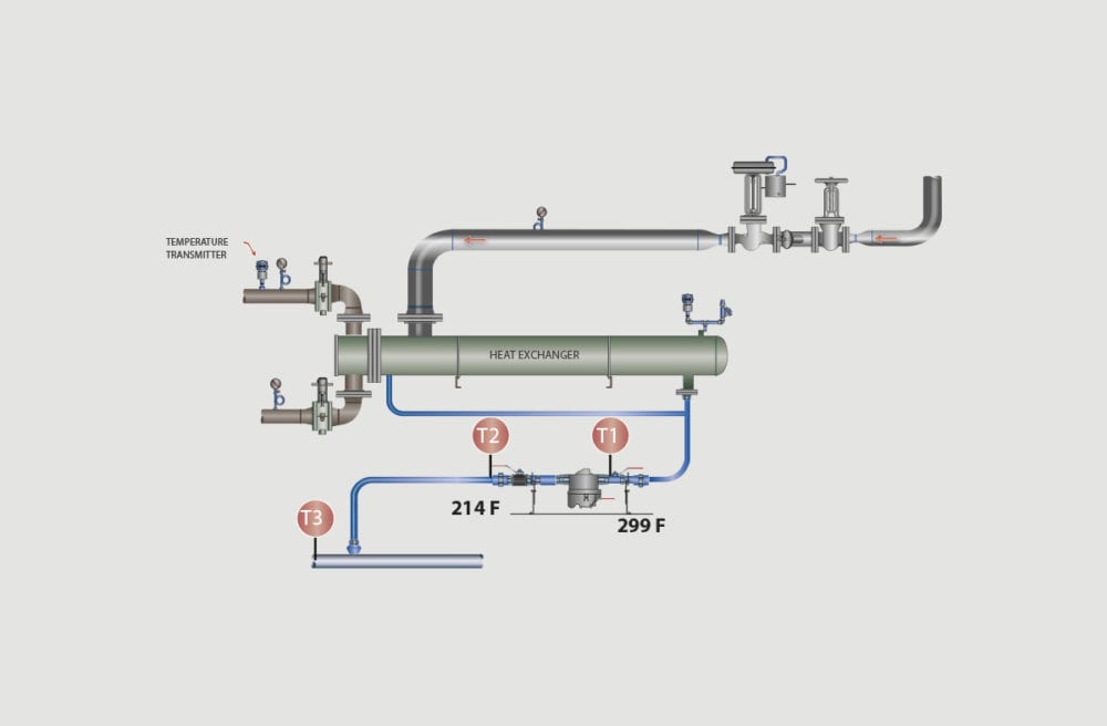
5. STEAM TRAP STATION SIZING EXAMPLE 1
- Heat exchanger application
- Steam line pressure = 35 psig
- Safety valve setting on the steam line = 150 psig
- Heat exchanger steam flow requirement = 8,000 lbs. per hour
- Delivery pressure to the heat exchanger = 35 psig
- P1 = 35 psig
- Pressure drop across the control valve = 5 psig
- P2 = 35 – 5 or 30 psig
- Pressure drop in the heat exchanger = 10 psig
- P3 = 30 – 10 psig or 20 psig
- P3 is the inlet pressure to the steam trap station
- Backpressure in the condensate line = 5 psig
- P5 = 5 psig
- Steam trap station outlet pressure will be P5 + P4
- Rise in condensate piping after the steam trap (distance 10 feet) = 5 psig
- ½ psig for each foot rise
- Therefore, P4 = 5 psig for the rise in the condensate piping and the pressure at P5 (5 psig) or 10 psig
- Steam trap differential pressure = P3 (20 psig) – P4 (10 psig) = 10 psig (differential pressure)
- Steam trap selection:
- Mechanical steam trap
- Steam trap orifice rated for a maximum pressure of 150 psig
- Steam trap sizing factor = 2 to 1
- Capacity or 8,000 x 2 = 16,000 lbs. per hour
- Steam trap sizing differential = 10 psig
- The steam trap station must be able to flow 16,000 lbs. per hour with a 10 psig differential pressure and a maximum orifice pressure rating of 150 psig.
6. STEAM TRAP STATION SIZING EXAMPLE 2
- Steam line drip leg application
- Steam line pressure = 150 psig
- Safety valve setting on the steam line = 200 psig
- Condensate flow requirement = 190 lbs. per hour
- P1 = 150 psig
- P2 = 25 psig (backpressure in the condensate return line) + 5 psig (rise of condensate pipe – 10 feet rise up to the condensate line)
- Flow = 190 lbs. per hour
- Thermostatic steam trap is selected
- Sizing factor is 3 x capacity, or the steam trap will have to pass 570 lbs. per hour
- Differential pressure (P1 – P2 = ΔP) or (150 psig – 30 psig) = 120 psig
- Steam trap with a orifice rated for 200 psig with a capacity of 570 lbs. per hour at a differential pressure of 120 psig and a maximum steam trap orifice pressure rating of 200 psig or higher
7. STEAM TRAP STATION SIZING EXAMPLE 3
Steam to a modulating process requires the following information:
- Determine the maximum pressure on the steam line supplying the process = 150 psig
- The steam trap needs to be rated for 150 psig @ 366°F
- The orifice in the steam trap will be rated for a pressure equal to or greater than 150 psig
- P1 (inlet pressure to the control valve) = 75 psig
- P2 (outlet pressure from the control valve to the heat exchanger) = 60 psig
- P3 (pressure drop at the heat exchanger) = 10 psig from TEMA sheets
- P4 (inlet pressure to the steam trap) = 50 psig
- P5 = outlet pressure from the steam trap = 0 psig (atmospheric tank system – gravity drainage)
- P6 = condensate line pressure – atmospheric tank
- Condensate flow rate = 3,624 lbs. per hour
- Sizing factor = minimum of 1.5 to 1, prefer 2 to 1 = 7,248 lbs. per hour
Conclusion: The steam trap should have a capacity of 7,248 lbs. per hour at a differential pressure of 50 psig and an orifice rating of 150 psig or more.
8. STEAM SIZING CONCLUSION
Steam trap sizing requires experience in the operating characteristics of many different pieces of equipment. The end result depends on the quality of the data. Plants must know all operating characteristics to select the proper steam trap station.
Some of these operating characteristics include the following:
- the design pressure or maximum steam pressure,
- the operating pressure,
- the return line pressure,
- the equipment condensing rate,
- the startup time and load, and
- the equipment use: intermittent or continuous.
The steam trap piping size can be selected after sizing the orifice. High condensate capacity steam traps will be available only in larger pipe sizes. If the heat transfer equipment has a 2” piping outlet, then do not select a ½” steam trap, as condensate flow would be restricted. Always select a steam trap with a connection equal to or larger than the process outlet connection: a 1.5” process outlet = 1.5” steam trap.
Many industries use ¾” steam trap piping as a minimum size to provide piping rigidity and, most importantly, standardization.
It is very important to obtain accurate capacity data for each process applications.


