No. 57 – Energy Items for Steam
Do you want this article in PDF format? Download it here:
Download a PDFCONTENTS
VENTING STEAM: THE LARGEST ENERGY LOSS IN STEAM SYSTEMS. 5
- Overview.. 5
- Why Do Plants Vent Steam to the Atmosphere?. 5
- Improper or No Steam Balancing of the Steam System.. 5
- Flash Steam Vented to the Atmosphere. 7
- Blowthrough Steam.. 8
- Unbalanced Steam Header Pressure. 9
- Deaerator Noncondensable Vent 10
- How to Eliminate Steam Venting. 11
- Modulating Steam System.. 11
- Nonmodulating Steam Systems. 12
- Thermocompressing. 13
- Process Outlet Temperatures Above 240°F.. 13
- Conclusion. 13
THE PRESSURIZED CONDENSATE RECOVERY SYSTEM: THE SOLUTION TO INCREASING A STEAM SYSTEM’S THERMAL CYCLE EFFICIENCY.. 15
- What Is a Pressurized Condensate System?. 15
- Why Maintain a Pressurized Condensate System? To Increase Efficiency and Reduce
- Energy Costs. 16
- What Are the Savings?. 18
- Standard Condensate Return System.. 18
- Typical Details of One Steam Application in a Process Plant 19
- Example 1: Steam Process Conditions. 20
- Summary of Energy Losses With a Typical Vented Condensate Return System.. 20
- Pressurized Condensate System.. 22
- Implementing a Pressurized Condensate System.. 22
- Summary of the Energy Savings by Implementing a Pressurized Condensate System 24
- New Pressurized Condensate System.. 26
- Components Required for a Pressurized System.. 26
- Pressure Control System.. 26
- Flash Tank or Deaerator. 27
- Pressurized Condensate. 27
- Condensate Line Sizing. 27
- How to Get Started. 27
STEAM BALANCING: THE FIRST STEP IN STEAM SYSTEM OPTIMIZATION.. 29
- What Is Steam Balancing?. 29
- Why Steam Balance Print(s) Are Not Achieved. 31
- Accomplishing a Steam Balance. 32
- End Results of a Steam Balance. 32
- Steam Balance Example 1. 33
- Steam Balance Example 2. 34
- Steam Balance Example 3. 35
- What Are the Benefits of Developing a Steam Balance?. 35
- What to Include in a Steam Balance. 36
- Conclusion. 37
STEAM AND CONDENSATE SYSTEM LEAKS ARE UNACCEPTABLE IN TODAY’S STEAM SYSTEM OPERATIONS: LEAKAGE COSTS AND SOLUTIONS. 39
- What Are the Major Causes of Steam Leaks?. 40
- Threaded Pipe Connections. 40
- Flanged Connections. 40
- Standard Type Valves. 41
- Internal Leakage. 41
- Valve Packing. 42
- Water Hammer. 43
- Other Causes. 43
- Other Issues. 43
- Solutions to Prevent Leakage. 44
- How to Determine Losses From Steam Leaks. 46
- How to Determine the Diameter of the Leak Path. 47
- Determining P1. 47
- What Are the Emissions?. 47
- How Much Do Steam Leaks Cost?. 48
- What Are the Costs?. 48
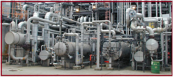
VENTING STEAM: THE LARGEST ENERGY LOSS IN STEAM SYSTEMS
1. Overview
Figure 1. Example of Steam Plant Operation: No Steam Venting
With today’s competitive international market, all plants need to reduce operating costs, and lowering energy consumption can have a positive impact on the bottom line. A plant’s steam and condensate systems cannot afford to vent any utility steam, blowthrough steam, or flash steam to the atmosphere. An additional benefit of not venting steam is a significant reduction in emissions in the boiler operation.
Any steam venting from the steam and condensate system is the top reason for lost energy in today’s steam systems. Can this objective be accomplished? Yes. Many plants have accomplished the goal of not venting steam, and they were rewarded with a high steam system thermal-cycle efficiency.
Of course, lowering energy costs also makes the plant more profitable and better able to compete in today’s international market.
2. Why Do Plants Vent Steam to the Atmosphere?
There are several reasons that plants vent steam to the atmosphere. However, with modifications using today’s technology, steam and condensate systems do not need to vent steam.
2.1. Improper or No Steam Balancing of the Steam System
The steam balance is always the first necessary part in any steam system optimization and management program. The valuable knowledge gained from a steam balance can help plant engineers use the steam system in the most efficient way, and this knowledge also provides essential insight that can support efforts to increase the steam system’s thermal-cycle efficiency. The perfect steam balance has no energy losses from steam venting, excessive low-pressure steam venting, flash steam venting, condensate loss, and so on.
However, a high percentage of plants do not have a steam balance program, which typically leads to the following results:
- flash steam being vented;
- utility steam being vented to meet the process steam demands;
- blowthrough steam vented from the following:
- process blowthrough,
- bypass valves opened, and
- steam trap station failures; and
- low-pressure nonutilized steam.
Ideally, every plant should strive to achieve the highest steam thermal-cycle efficiency possible. The steam balance provides the information needed to achieve this goal.
Figure 2. Example of an Unbalanced Steam System
The optimal steam balance system ensures that the end users (steam processes) can achieve the correct volume of energy at the correct steam pressure/temperature with the required steam quality.
Table 1. Example of Steam Venting Costs
| Steam cost per 1,000 lbs. | $3.75 |
| Steam pressure | 125 |
| Steam loss (pph) | 12,784 |
| Cost/hr. | $47.94 |
| Days/yr. | 350 |
| Cost/yr. | $402,726.00 |
| CO2 emissions/yr. | 14,995 |
| NOX | 11,783 |
2.2. Flash Steam Vented to the Atmosphere
Figure 3. Flash Steam Venting
A typical steam system will incorporate an atmospheric condensate receiver that allows the flash steam to vent to the atmosphere. There are systems such as modulating process steam systems where the condensate system needs to operate at zero pressure; therefore, the flash steam is required to be consumed or vented. Unfortunately, a large number of plants vent the flash, which is a substantial energy loss.
Table 2. Example of Flash Steam Venting Costs
| Steam cost per 1,000 lbs. | $6.21 |
| Steam pressure | 175 |
| Steam loss (pph) | 3,196 |
| Cost/hr. | $19.85 |
| Days/yr. | 350 |
| Cost/yr. | $166,728.00 |
| CO2 emissions/yr. | 3,748,839 |
| NOX | 2,947 |
Figure 4. Flash Steam Venting to the Atmosphere
A small amount of flash steam being vented to the atmosphere has a significant energy loss ($26,220.00 per year).
Table 3. Example of Flash Steam Venting Costs
| Steam cost per 1,000 lbs. | $6.11 |
| Steam pressure | 24 |
| Steam loss (pph) | 510 |
| Cost/hr. | $3.12 |
| Days/yr. | 350 |
| Cost/yr. | $26,220.00 |
| CO2 emissions/yr. | 587,794 |
| NOX | 462 |
2.3. Blowthrough Steam
Blowthrough steam is generated in two primary ways. Process blowthrough steam is required for a limited number of processes to ensure proper condensate drainage. However, bypass valves around components that allow steam to freely flow into the condensate header, largely as the result of steam trap station failures, are totally unacceptable for steam system operations.
Figure 5. Blowthrough Steam
The lack of a proactive steam trap station management program allows failed steam traps to leak or blow steam into the condensate header. Eventually, this steam has to be vented to the atmosphere at the condensate collection tank system.
All of these items are easily correctable.
Table 4. Example of Energy Losses From a Small Steam Trap Station Population
| Steam cost per 1,000 lbs. | $8.45 |
| Steam pressure | 100 |
| Steam loss (pph) | 2,125 |
| Cost/hr. | $11.69 |
| Days/yr. | 350 |
| Cost/yr. | $98,204.00 |
| CO2 emissions/yr. | 2,486 |
| NOX | 1,945 |
2.4. Unbalanced Steam Header Pressure
Figure 6. Steam Venting From an Unbalanced Steam Header
Steam header balancing can be a struggle, given that process steam demands frequently change to meet production requirements.
Unbalanced header pressure can be caused by instantaneous process changes, steam turbine operation, and uncontrolled pressure-reduction stations.
Unfortunately, an easy way to stabilize the steam header pressures is to vent steam to the atmosphere to reduce or eliminate overpressurized operations.
Table 5. Example of the Cost of Steam Venting From an Unbalanced Steam Header
| Steam cost per 1,000 lbs. | $4.90 |
| Steam pressure | 40 |
| Steam loss (pph) | 2,111 |
| Cost/hr. | $10.36 |
| Days/yr. | 350 |
| Cost/yr. | $87,050.00 |
| CO2 emissions/yr. | 2,403,212 |
| NOX | 1,822 |
2.5. Deaerator Noncondensable Vent
Figure 7. Deaerator Venting
In a steam deaerator, steam serves as the scrubbing agent to reduce the partial pressures of the gases being removed.
With the scrubbing action occurring, the deaerator must vent the noncondensable gases to the atmosphere. The only acceptable steam venting from a steam system operation is the deaerator venting noncondensable gases along with a very small percentage of steam.
With the high cost of steam today, the deaerator vent must be investigated to ensure that excessive steam venting does not occur. All deaerators need to have dissolved oxygen testing conducted at least every three months, and noncondensable venting must be adjusted accordingly to achieve maximum performance.
Table 6. Example of Energy Costs for an Aggressively Overventing Deaerator Vent
| Steam cost per 1,000 lbs. | $5.45 |
| Steam pressure | 8 |
| Steam loss (pph) | 292 |
| Cost/hr. | $1.51 |
| Days/yr. | 350 |
| Cost/yr. | $14,494.00 |
| CO2 emissions/yr. | 332,920 |
| NOX | 262 |
3. How to Eliminate Steam Venting
There are two types of steam systems in plant operations today.
3.1. Modulating Steam System
Figure 8. Flash Steam Vent Condensate
A modulating steam/condensate process means the process application has a steam control valve that modulates the steam to the process. The steam control valve can operate from 0% (closed) to 100% (fully open) and anywhere in between.
The modulating steam system’s operational design requires the condensate from the processes to be recovered by a gravity (0 psig) condensate system.
The condensate system will incorporate a condensate receiver that allows the flash steam to vent to the atmosphere. The venting of the flash steam ensures the condensate receiver is never pressurized.
To prevent the flash steam loss to the atmosphere, plants install devices such as flash steam vent condensers in the flash steam vent line.
A flash steam vent condenser is incorporated in the system to recover the flash steam by using an external heat exchanger (condenser).
The vent condenser (heat exchanger) will consume the flash steam by heating air, water, or some other process fluids. The vent condenser is designed for the application to ensure proper operation.
Figure 9. Steam Vent: Air Condenser Design
The process fluid consumes the flash steam and allows the condensate to drain back into the condensate tank. Therefore, the flash steam is consumed, and the condensate is recovered.
All vented condensers are engineered for the application.
3.2. Nonmodulating Steam Systems
A nonmodulating steam condition means there is no control valve modulating steam flow to the process. If there is a steam control valve, it always maintains a steam pressure to the process that is higher than the pressure in the condensate recovery system. This system is classified as a nonmodulating steam process.
A nonmodulating process steam system provides a steam pressure to the process that will provide a differential pressure on the drain device (steam control valve or steam trap station).
Examples of nonmodulating steam processes include the following:
- steam tracing,
- processes with temperatures above 240°F,
- drip leg steam traps,
- process heaters,
- reboilers,
- corrugators.
The typical plant operation is not designed to accommodate the higher condensate temperatures and additional flash steam generated by the nonmodulating steam system. In these operations, the condensate and flash steam are delivered to a vented condensate tank system. The flash steam is then vented to the atmosphere, and a substantial energy loss occurs.
However, flash steam can be recovered by using a cascade system that incorporates a flash tank system or by using a thermocompressor system.
Figure 10. Flash Tank System
The two-phase flow (flash/condensate) from the process discharge can be directed to the pressurized flash tank for separation. The flash steam then can be delivered to a lower-pressure steam header system. This method is referred to as a cascading flash steam system.
4. Thermocompressing
Figure 11. Flash Steam Recovery With a Thermocompressor System
A large number of plants do not have a need for low-pressure steam; therefore, the cascade steam system is not a benefit. Another method to recover the flash steam is to use a thermocompressing system. Thermocompressing takes the low-pressure steam and produces a higher, usable steam pressure.
The thermocompressor is a simple device that has existed for many years. It has a nozzle where high-pressure steam is accelerated into a high-velocity fluid. The high velocity entrains the low-pressure steam from the flash tank by momentum transfer and then recompresses it in a divergent venturi. The result is an intermediate steam pressure that is useful to the plant operation.
4.1. Process Outlet Temperatures Above 240°F
There are processes where the outlet temperatures are at or above 240°F, which means the steam control valve will never reduce the steam pressure below the steam pressure equal to the process temperature.
Example:
- Process outlet temperature: 310°F
- Steam pressure @ 310°F: 90 psig
The steam pressure will not be lower than 90 psig; therefore, the condensate can be discharged into a flash tank, and the flash can be used in a cascade system or thermocompressing system.
5. Conclusion
Tomorrow would be a good day to start following the road map to prevent any steam from venting to the atmosphere.
Figure 12. Plant Operation: No Steam Venting
THE PRESSURIZED CONDENSATE RECOVERY SYSTEM: THE SOLUTION TOINCREASING A STEAM SYSTEM’S THERMAL CYCLE EFFICIENCY
Figure 13. New Pressurized Condensate Tank System
Pressurized condensate systems can provide plants with a minimum of between 15% and 35% savings in fuel costs when compared to a conventional atmospherically vented condensate system. That is a tremendous opportunity for facilities, since fuel prices have gone up and are expected to increase even further. The pressurized condensate system is not a luxury; rather, it is a necessary component to maximize and increase the steam system’s efficiency. Unfortunately, not all steam plants or steam applications can implement a high-pressure condensate return system. Therefore, proper preliminary engineering assessment, design review, and knowledge of the application are necessary to ensure a successful condensate system. In the examples that are included in the technical paper, we achieved an energy savings of $ 226,700.00 by implementing a 50 psig pressurized condensate system. The project was implemented at a cost of $305,400.00, yielding a 1.3-year payback.
1. What Is a Pressurized Condensate System?
Pressurized condensate recovery systems operate continuously at a pressure above 15 psig, and the condensate recovery system is not vented to the atmosphere. The pressure in the condensate system is sustained by the dynamics of the system or a systematic control process loop. Typical condensate systems operate with backpressure because their condensate line is improperly sized for two-phase flow and because plants neglect steam trap stations blowing steam into the condensate line. These items alone can cause unwanted and uncontrollable pressure in the condensate recovery system. A pressurized condensate recovery system differs in that the condensate return line pressure is systematically controlled and managed to a predetermined set point that matches the peak performance level of the steam system process and integrates into the dynamics of the steam balance.
Four classifications of condensate systems are used in plants today:
- gravity or atmospheric (condensate line pressure maintained at or close to 0 psig),
- low pressure (1 to 15 psig),
- medium pressure (16 to 99 psig), and
- high pressure (100 psig or higher).
Pressurized condensate system technology is not new in the steam world; these systems can be documented back to 1941. Though the technology may be considered old, it has been overlooked over the years due to relatively inexpensive fuel prices. As fuel prices have risen and, with them, the need for optimization to reduce overall operational costs, industrial plants are paying more attention to these systems, because they have proven to be a significant way to decrease expenses. Pressurized condensate systems are considered one of the top three items to optimize a steam system with a very attractive payback for the investment.
2. Why Maintain a Pressurized Condensate System? To Increase Efficiency and Reduce Energy Costs
The best reason to use a pressurized condensate system is the remarkable energy savings that plants can oftenachieve with a low implementation cost.Any condensatethatisnotcontaminatedinaprocess application needs to be returned to the boiler operation to complete and increase the steam system’s thermal cycle. Condensate contains a high quantity of sensible energy. If the sensible energy is not properly returned to the boiler operation, a large percentage, if not all, of this energyis lost.
Condensate that is returned to the boiler operation will require the condensate temperature to be raised to the saturated temperature of the steam boiler’s operating pressure. To accomplish this task, energy is introduced at the deaerator and the boiler. The deaerator will add energy to heat
Figure 14. Atmospheric Condensate System
the condensate to a temperature where noncondensable gases will be removed from the fluid. The boiler will add the energy for phase change to occur at the boiler operating pressure.
The higher the temperature or pressure (direct relationship in steam) of the condensate being returned to the boiler plant, the less energy that is required to raise the temperature of the condensate back to the saturated temperature of the boiler operatingpressure.
The most efficient system is a condensate return system controlled at a pressure as close to the boiler operating pressure as possible. In a perfect system, the steam system would operate at 150 psi, and the pressurized condensate system would operate at 149 psi. However, the limitation is the type of steam and condensate system: the plant must consider elements such as line sizes, distances, steam trap station differential, and elevations. With these variables in the system, a typical target for pressure differential between the steam supply and condensate return is between 30% and 45%. All pressurized condensate systems must be thoroughly evaluated before selecting the condensate return line pressure.
3. What Are the Savings?
To determine the cost savings of a standard condensate system vs. a pressurized condensate system, it is important to review all operational parameters.
Review the following prints and detailed printouts of the steam and condensate system:
- Detail 1: Boiler operating steam pressure
- Detail 2: Fuel input into the boiler (Btus)
- Detail 3: Steam flow output from the boiler (Btus)
- Detail 4: Steam flow Btus
- Detail 5: Condensate system operating pressure
- Detail 6: Percentage of condensate loss
- Detail 7: Condensate loss (lbs./hr.)
- Detail 8: Condensate flow to condensate tank (lbs./hr.)
- Detail 9: Flash steam flow rate (lbs./hr.)
- Detail 10: Pumped condensate flow to deaerator
- Detail 11: Condensate Btus to deaerator
- Detail 12: Make-up water flow rate to deaerator
- Detail 13: Deaerator operating pressure
- Detail 14: Steam flow to deaerator for heating feedwater
3.1. Standard Condensate Return System
A standard condensate system, where condensate is recovered into an atmospheric condensate tank system, will have inherent energy losses. These energy losses are as follows:
- condensate is allowed to cool to 212°F,
- a large amount of flash steam is generated,
- flash steam is allowed to escape to the atmosphere, and
- flash steam losses increase the quantity of make-up water.
All condensate and make-up water, which will become boiler feedwater, will require energy input to bring the energy level up to the saturated temperature of the boiler operating pressure. Reducing the differential energy levels (condensate and make-up water) to the boiler saturated energy level will increase the steam system’s thermal cycle efficiency.
Figure 15. Condensate System With All Location Details
4. Typical Details of One Steam Application in a Process Plant
Application: Steam process
Steam pressure supplied to the process: 150 psi (before a control valve) equivalent
Steam temperature: 366°F
Steam pressure at the process: 150 psi pressure)
Steam flow rate: 24,000 lbs./hr. (minimum)
Operation: 8,760 hrs./yr.
Condensate line pressure: 0 psig (vented to the atmosphere and mechanically pumped back to the boiler plant)
Cost of steam (per thousand lbs.): $5.24
5. Example 1: Steam Process Conditions
A steam requirement for the process applications is rated at 24,000 lbs. per hour, which provides 24,000 lbs. per hour of condensate. Condensate is drained from the steam process through a standard steam trap station. The steam trap station discharges condensate into a vented condensate receiver system. When condensate is drained from the process at a given pressure (150 psi) and passes through a steam trap station to a lower pressure (0 psi @ 212°F), then a percentage of the condensate will flash to steam. The vented condensate receiver tank allows the flash steam to be vented to the atmosphere and ultimately leads to a loss of energy, and the flash steam loss will increase the quantity of make-up water. The condensate is allowed to be reduced to 212°F, which will require an influx of energy at the deaerator and boiler to achieve phase change at 150 psig. The deaerator will use essential steam (steam off the main header) to heat the low temperature condensate and make-up water up to the operating saturated conditions of the deaerator operating pressure.
6. Summary of Energy Losses With a Typical Vented Condensate Return System
Summary of Operational Costs:
- Boiler fuel cost (yearly): $1,167,301.00
- Flash steam losses: $162,043.00
- Steam for deaerator operation: $64,657.00
- Total energy loss cost: $226,700.00
The atmospheric system has a total energy loss of $226,700.00 per year as a result of flash steam loss, deaerator steam requirements to heat the low temperature and make-up water, and the cost of additional chemicals.
7. Pressurized Condensate System
Quantifying the losses in terms of money is the first step to developing an improvement plan. Pressurized condensate systems are an excellent method for reducing these losses by 75% or more, depending on the current operating conditions of the steam and condensate system. Understanding the dynamics of the current system and the dynamics of implementing a pressurized system will lead to a successful implementation.
7.1. Implementing a Pressurized Condensate System
In a pressurized condensate system, typical losses will be greatly reduced or eliminated by the dynamics of the pressurized system. The pressurized system will have several benefits.
- It will increase the condensate temperature or sensible energy level. The condensate temperature in the pressurized system is now at the temperature of the deaerator or higher. Therefore, the deaerator does not require essential steam (energy) to heat the condensate, saving essential steam.
- Another benefit to pressurized condensate is that condensate has not been exposed to the atmosphere and has not absorbed any noncondensable gases. The condensate does not have to go through the deaerator process. In several types of installations, the condensate can be delivered directly into the boiler.
- It will reduce make-up water usage. With the flash steam being recovered in a pressurized system, no flash steam is lost. Thus, the only need for make-up water is to replenish the deaerator’s noncondensable vent losses. The make-up costs are negligible in a pressurized system. Reducing make-up water also will reduce boiler blowdown, thus reducing another energy loss in the boiler operation.
- It will reduce the flash steam quantity that is generated, which will reduce the condensate pipe sizing requirements and reduce the condensate losses (1 lb. of flash steam is 1 lb. of condensate).
- It will reduce the energy differential (condensate vs boiler operating condition. This will reduce the amount of fuel input into the boiler to raise the feedwater to the appropriate phase change temperature.
- It will enable the plant to use the flash steam from a pressurized system.
Before changing everything to a pressurized condensate system, the first step is to ensure that the steam/condensate system and the steam processes will be able to operate in the new conditions. Condensate and flash steam (two-phase flow) discharging from a nonmodulating or elevated temperature process can operate in a pressurized condensate system.
- A nonmodulating steam condition refers to a steam system process where no control valve modulates the steam flow into the process to maintain a desired temperature or pressure. A process steam system that lacks a modulating steam control scheme for the process provides a constant steam pressure to the process. Therefore, if the condensate recovery system has a controlled pressure, there is a constant pressure differential across the steam trap stations or condensate discharge control valve.
Figure 16. High Temperature Process Outlet Temperature of 320°F
- In a high-temperature process where the process temperature is higher than the pressurized condensate system, there will be differential pressure across the drain devices, such as the steam trap station or condensate discharge control valve.
Example: If the process temperature is at 320°F, steam pressure to the process has to be higher than 75 psig. With steam pressure of 75 psig to the heat exchanger, P4 (in the example) will have a pressure of 70 psig or greater, and the condensate line pressure could operate at 30 psig.
Here are some examples of steam systems and processes:
- steam tracing,
- process ovens,
- process heating systems,
- steam line condensate removal steam trap stations,
- paper machines,
- rubber processes,
- press operations,
- reboilers,
- corrugators,
8. Summary of the Energy Savings by Implementing a Pressurized Condensate System
Using the same example of an atmospheric condensate system and implementing a pressurized condensate system (increase the condensate pressure to 50 psig), the optimization results are as follows:
- Boiler fuel cost (yearly): $1,167,301.00 $940,601.00
- Flash steam losses: $162,043.00 $0.00
- Steam for deaerator operation: $64,657.00 $0.00
Implementation of a condensate system that is operating at 50 psig instead of 0 psig resulted in a savings of $226,700.00.
Note: The flash steam was consumed by the deaerator operation, and a percentage of remaining flash steam was consumed by an end user.
8.1. New Pressurized Condensate System
Figure 17. New Pressurized Condensate System
- Condensate line now operates at 50 psig
- Flash is operating at 50 psig with the flash steam going to the deaerator
- Deaerator is operating at 50 psig
- Condensate is directed to the storage side of the deaerator
- Steam system is balanced and the Steam System Thermal Cycle Efficiency is increased
9. Components Required for a Pressurized System
Several components are required to implement a pressurized condensate system.
9.1. Pressure Control System
A pressure control system controls the condensate pressure to a predetermined set point. The condensate pressure must be managed. One method is to use a backpressure control valve with a controller. An easier method is to use the flash tank discharging into the steam system that has a controlled steam pressure.
9.2. Flash Tank or Deaerator
Installing a flash tank system that delivers flash steam to a controlled steam system is an excellent way to operate the pressurized condensate system. One user of flash steam is the deaerator, which normally operates below 15 psig. Most steam systems have several operating steam pressures, so the flash steam can accept the cascaded steam.
Another method uses a thermocompressor to raise the flash steam’s pressure and reintroduce it into the steam processes or deliver the steam into a plant steam system pressure distribution system. Installing a new deaerator or using the current deaerator, which can operate at a higher pressure, is a third method of receiving the pressurized condensate. The deaerator is operated at a predetermined operating pressure that is the same as the pressure in the pressurized condensate system. The condensate temperature is already elevated, and there will be a reduced quantity of flash steam, which is normally consumed by heating the make-up water.
9.3. Pressurized Condensate
Pressurized condensate does not have to be deaerated and can be pumped directly back into the boiler. The condensate has not been exposed to the atmosphere; therefore, it has not obtained any noncondensable gases.
9.4. Condensate Line Sizing
Condensate line sizing always needs to be checked to ensure it has the proper design to operate in a pressurized operation. Typically, the condensate line size required is reduced by the lower quantity of flash steam, which normally requires more area in atmospheric or very low operating pressure condensate lines. Velocities are also reduced due to the lower flash steam quantity, thus eliminating the normal water hammer issues with high condensate line velocities.
10. How to Get Started
There are many reasons to implement a pressurized condensate system and no reason not to implement one. The first step is for plant personnel or an outside firm experienced in pressurized condensate systems to conduct a steam and condensate assessment. The assessment will provide the knowledge of the benefits of pressurized condensate system and, more importantly, the cost of implementation.
STEAM BALANCING: THE FIRST STEP IN STEAM SYSTEM OPTIMIZATION
1. What Is Steam Balancing?
Creating and maintaining a steam balance is the most efficient way to gain knowledge of all aspects of a plant’s steam system, such as steam generation, distribution, end users, and condensate-recovery systems. The steam balance is always the first step in any steam system optimization and management program.
The valuable knowledge gained from developing or updating a steam balance leads to setting a road map to use the steam system in the most efficient way and provides the understanding necessary to increase steam system thermal cycle efficiency. Every plant needs to achieve the highest steam thermal cycle efficiency possible.
A steam system in perfect balance has the end users (steam processes) achieving the correct volume of energy at the correct steam pressure/temperature with the proper steam quality. The perfect steam balance has no energy losses from steam leakage, excessive low-pressure steam venting, flash steam venting, condensate loss, etc.
Establishing the correct steam balance can be very challenging because of all the different dynamics in a steam system, such as modulating steam loads, variable production times, unaccountable losses, insulation inefficiencies, turbine operation, etc.
Figure 1 shows a close-to-perfect steam balance that has steam being produced at 200 psig and delivered to the process. The process consumes the 200 psig (latent energy) of the steam, and the condensate (sensible energy) is removed from the process. The end-user process requires the latent energy of steam. When that latent steam is released, there is no temperature or pressure variance, and the condensate that contains the sensible energy is returned to the deaerator operation at a high pressure. The condensate system, which is operating at 198 psig, returns the condensate (high-pressure return system) back to a high-pressure deaerator system that delivers the feedwater at an elevated temperature (198 psig = 387°F) into the boiler operation.
The advantages of a steam system in perfect balance are as follows:
- higher sensible energy content in the condensate;
- reduced flash steam, with no need for flash steam recovery, because the deaerator will consume the small percentage of flash steam;
- smaller diameter condensate piping;
- higher feedwater temperatures, thus a higher boiler efficiency; and
- higher steam system thermal cycle efficiency.
Figure 18. A Steam System in Perfect Balance (If This Could Be Accomplished)
However, a perfect steam balance cannot exist for several reasons, because of modulated steam pressures or flows to system processes and the dynamics of condensate drain devices. The condensate system’s dynamics can also limit on how high a pressure the plant can maintain in the condensate return system.
Even so, the plant’s responsibility is to strive to create a system as close to the example as possible so it can achieve a high steam system thermal cycle efficiency. The consumers, or end users, of the steam demand the correct quantity and 100% steam quality at a given specific pressure/temperature, and it is up to the plant to manage the steam balance to meet the end users’ requirements. The end users’ steam demands and steam quantity constantly vary, so achieving a high steam system thermal cycle efficiency requires plants to have a well-documented steam balance to meet the production requirements.
2. Why Steam Balance Print(s) Are Not Achieved
A high percentage of the time, knowledge of the steam system is fragmented. The boiler plant personnel know the boiler plant operation well, and process personnel understand the process steam operation. Meanwhile, most of the time, the steam distribution and condensate system are left in limbo and not attended to by anyone. Often, the condensate system is omitted from the total steam system balance, even though it accounts for 16% of the overall energy in the steam vapor. The flash steam is a critical part of the steam balance, so the flash steam should be recovered by some means to ensure steam thermal cycle efficiency.
Figure 19. Steam Balance Example
In addition, it may be difficult to establish a single or dual set of prints because the CAD library might contain multiple different PID prints that were created over the years by many different engineers using different formats. Some plants do not keep their CAD prints up-to-date, which makes the task even more difficult to accomplish. Even so, plants must remember that developing a steam balance print offers a significant return on the investment.
3. Accomplishing a Steam Balance
It is impossible to optimize a steam and condensate system without a steam balance, because it requires a complete understanding of the system. The easiest and best method to deliver that steam system understanding is to create a steam balance flow diagram.
The steam balance flow diagram can be accomplished in many ways, from a fully developed document completed in Aspen software to a simple flow diagram completed with Microsoft Visio. The key point is to have a steam balance document for plant personnel.
4. End Results of a Steam Balance
Implementing a perfect steam balance between steam generation, distribution, end-user requirements, and condensate recovery can be an extremely challenging goal in any industrial steam plant operation. An industrial plant can have several different steam-generating sources and a multitude of end users with varying steam pressure and steam flow demands. The steam turbine operation for electrical generation or drive units plays an important role in the balance, and the steam pressure letdown valves (pressure-reducing valves) need to be minimized to ensure maximum steam flow to the steam turbine operation.
Four types of condensate recovery systems are added into the balance, making the system dynamics even more complex. Today, to meet production requirements, plants are continuing to update and make process changes that will affect the steam balance. Therefore, steam balancing is a continuous program, not a one-time venture.
The steam balance will eliminate the waste of unusable low-pressure steam being vented to the atmosphere by balancing the steam flow to the end users (steam turbines, heat exchangers, reboilers, etc.), then discharging the condensate/flash steam to the steam cascade systems to successfully end the steam process with the correct amount of low-pressure steam. If this is not accomplished, then the low-pressure steam is thermocompressed to medium steam pressure grids until balance is achieved in the system.
4.1. Steam Balance Example 1
Figure 20. Example of a Steam Balance
The steam balance in Figure 20 was accomplished in a simple format, but it resulted in a substantial reduction in energy and emissions. The steam balance indicated that a pressurized condensate system could easily be instituted into segments of the process system using the current condensate system with minor capital costs, saving millions of dollars per year.
4.2. Steam Balance Example 2
The second sample steam balance in Figure 21 showed that a few minor steam piping changes would allow end users to consume low steam pressures, thus reducing the flash steam losses. Changes improved condensate drainage and further reduced the flash steam venting. The result was a higher steam system thermal cycle efficiency with reduced energy and emissions and increased reliability.
Figure 21. Steam Balance Example 2
4.3. Steam Balance Example 3
Figure 22. Steam Balance in Microsoft Visio
Figure 22 demonstrates different methods to recover the condensate under pressure, thus saving energy and reducing emissions for the plant operation. Switching from a low-pressure deaerator to high-pressure deaerator with condensate line changes allowed the return of condensate from nonmodulating processes to the high-pressure deaerator, resulting in higher steam system cycle efficiency.
5. What Are the Benefits of Developing a Steam Balance?
A steam balance is like the dashboard of your car: it will provide the drivers of the steam and condensate system with all information required to operate safely and efficiently. The knowledge to be gained includes the following:
- a better understanding of the steam and condensate system,
- the ability to set a road map for changes that will improve the system,
- opportunities to improve energy efficiency,
- opportunities to reduce emissions, and
- opportunities to increase reliability.
6. What to Include in a Steam Balance
A steam balance flow document provides all relevant steam and condensate information, such as steam flows, pressures, end users, pressure-reduction stations, turbines, boilers, condensate tanks, etc. The more detail added into a steam balance flow diagram, the more useful the document becomes to the plant operation.
Document the following items:
- All boilers or steam generators
- Steam output
- Operating steam pressures
- Safety valve set pressure
- Deaerator system
- Operating pressure
- Steam flows
- Make-up water system for the deaerator
- Flow rates
- Average temperature
- Steam turbines
- Supply pressures
- Extraction pressures
- Electrical or drive output
- Steam headers by operating pressure
- Steam pressure-letdown stations
- Inlet and outlet pressures
- Maximum and minimum flow rates
- End users or consumers
- Energy requirements
- Maximum and minimum
- Condensate headers
- Operating pressures
- Flow rates
- Flash tanks
- Integration into the system
- ASME stamping
- Condensate tanks
- Venting or not venting
- Pressure ratings
- Energy requirements
The list will grow as the steam balance process continues.
7. Conclusion
Every plant, regardless of size, from the smallest food processing plant to the largest refinery, needs to prepare a steam balance in a format that works for the plant’s operation. The steam balance does not have to be done in a complex software system to be beneficial to the steam system manager; it can be accomplished in a simple graphic software package. Whatever format is selected, the balance is the first step in increasing steam thermal cycle efficiency, which will reduce energy and emissions and increase profits.
Today, our plant may look like the one in Figure 23, with steam venting to the atmosphere, which can amount to tremendous steam losses.
Our target is for our plant to look like the one in Figure 24 in five or fewer years.
Figure 24. Target View in Five Years or Fewer: No Steam Losses
Today is a good day to get started: tomorrow may be too late.
STEAM AND CONDENSATE SYSTEM LEAKS ARE UNACCEPTABLE IN TODAY’S STEAM SYSTEM OPERATIONS: LEAKAGE COSTS AND SOLUTIONS
Figure 25. Steam Leakage at a Connection
Leaks are unacceptable in today’s industrial steam and condensate system. In fact, steam leakage is considered abnormal in daily plant operations. Yet steam and condensate leaks cost industrial plants millions of dollars in lost energy while increasing emissions, creating safety hazards, and lowering the reliability of plant operations.
One of the highest returns on a plant’s investment is correcting steam and condensate leakage and instituting operational changes to prevent any leakage from occurring again in the system. Changes that can eliminate leakage can include (but are not limited to) the following:
- component selection,
- installation practices,
- design,
- plant specifications,
- material selection, and
- operational practices.
Steam and condensate leakage is one of the top five opportunities for reducing energy and increasing reliability and safety in plant operations. Steam leakage results in the loss of both latent and sensible energy, while condensate leakage is the loss of sensible energy. Though plant personnel should pay attention to all utility losses, they should pay even greater attention to the costs and problems associated with those losses related to steam.
Steam and condensate leakage in the system can contribute to significant energy losses—as high as 9% of the overall energy consumption—in a plant’s operations. In fact, due to the high cost of these energy losses, the correction of steam and condensate leakage offers very lucrative paybacks. The greatest benefit of a proactive steam and condensate leakage correction program is that most leaks can be corrected without expending capital.
1. What Are the Major Causes of Steam Leaks?
Inveno Engineering, LLC has conducted hundreds of steam system audits and has found that the following items are the most common contributors to steam and condensate leakage in plants.
1.1. Threaded Pipe Connections
Figure 26. Threaded Connection Leakage
The number one cause of steam and condensate leaks is the use of threaded pipe connections (National Pipe Thread (NPT) connections) in a steam and condensate system. Pipe threads were developed in 1864 and have achieved very few improvements over time. The threads are prone to fail due to several issues that occur in a steam/condensate system.
One issue is the quality of the thread on the components. All threaded components need to be quality checked to ensure the thread meets the proper standard. There are many different thread standards: NPT, NPTF, BSP, BSPP, etc. When plants mix these standards, it will negatively affect installation and operation.
Expansion and contraction of the steam/condensate piping during system startup, operation, and shutdown can also cause leaks. The expansion and contraction can exceed a few inches in some cases, thus putting more demands on the threaded connection.
Oxygen and carbon acid corrosion in the system will attack the threaded connections. The result of the corrosion attack will be loss of the thread material, which will result in a leakage point.
The plant must carefully select lubricants for the threaded surfaces to ensure that they are compatible with system media and that they are able to perform at the temperatures found in the system. Often, during installation, threaded lubrications can negatively affect the process fluids or cause problems with process components. Using different types of lubrication materials on the threaded connections to prevent leakage has limited success.
1.2. Flanged Connections
When adding flanges to the steam system, consider the following three items for their installation and operation.
- Flange gasket materials: The gasket materials need to be rated for the maximum pressure and temperature.
- Expansion and contraction: Flanges are not designed to withstand significant side loading. Pipe guides should be used to ensure that flanges are only subject to axial movement.
- Torque specifications and torque sequence: It is crucial to know the proper torque specification for flanged connections prior to installation. Improper torque can damage the gasket and/or flange. It is also important to know the tightening pattern of the fasteners responsible for holding the flanged connection together. Failing to torque the fasteners in the correct order can lead to connection damage and failure.
1.3. Standard Type Valves
For a long time, gate and globe valves have been one of the most common valve styles used worldwide for flow control of the steam and condensate system media. The first gate valve was patented in 1839, with the last change in design in the 1940s.
Standard valves should never be based purchased on price but rather on operational considerations.
In recent years, technology in ball and butterfly valves has greatly improved, allowing these valves to operate at higher pressures and temperatures. Also, ball and butterfly valves have standard leakage rates that are extremely low compared to other valves and are tested or documented to the different internal leakage standards.
1.4. Internal Leakage
Figure 27. Internal Valve Leakage
The first and most important consideration when selecting a valve for steam service is the valve’s internal steam leak rate. Any valve in an isolation service for steam and condensate must be able to provide a tight shutoff in a closed position. The plant needs an approved, consistent method for documenting the internal leakage rate.
- American Petroleum Institute (API) 598, Valve Inspection and Test:This is the most widely used test specification in the world. It covers many types of valves but was developed primarily for consideration of isolation valves. The standard includes leakage rates and testing criteria for both metal-seated and resilient-seated valves.
- Manufacturers Standardization Society (MSS) SP61, Hydrostatic Testing of Steel Valves:This standard is similar to API 598 but has subtle differences in test holding times and leakage rates. It was developed to provide a uniform means of testing valves commonly used in the “full open” and “full closed” type of service. It is not intended for use with control valves. Refer to standard ANSI/FCI 70-2 for Control Valves.
- American National Standards Institute (ANSI/FCI): ANSI has defined six permissible steam leak rates for valves. As the valve’s class number increases, less steam leakage is observed across the valve. Any valve considered for steam service must have no less than an ANSI/FCI Class IV rating. Whenever possible, a Class VI rating is highly advised for positive shutoff.
1.5. Valve Packing
Standard gate and globe valves that use an older method of sealing the actuating stem from the internal steam/condensate flow areas to the outside operation of the valve (valve handle or stem) have a high leakage rate during steam/condensate leakage assessments.
Figure 28. Valve Packing Leakage
Standard gate and globe valves are unsupported in any position other than fully closed, at which time the seat surrounds the bottom end of the valve. Since the globe or gate is supported at the top by the valve stem and unsupported at the bottom, the force exerted by the system pressure causes the globe or gate to have movements other than a straight up and down. These different types of movements will damage the valve packing. As the valve packing is exposed to the steam or condensate media, it will result in valve leakage. The normal location of the steam or condensate leakage presents a safety hazard to personnel because the flow is directed toward the operating handle of the valve.
Without a proactive maintenance program, standard packing on steam isolation valves will fail and leak steam or condensate during operation. And steam valve failures will lead to energy losses and production issues.
1.6. Water Hammer
Water hammer in the steam and condensate system can produce pipe connection failures that result in system leaks.
Solution: Water hammer should not occur in the steam and condensate system. If water hammer exists, the issue must be resolved. Causes and solutions to water hammer can be reviewed in Inveno Engineering, LLC’s Best Practice 11, “The Number One Problem in a Steam System—Water Hammer.”
1.7. Other Causes
Erosion can also cause steam leaks. Steam is very erosive. The term “wiredraw” refers to the ability of the steam to actually cut metal. Plant personnel must be very proactive with steam leakage because of the risks of erosion: as equipment erodes over time, steam leaks will increase, causing an even more serious issue.
2. Other Issues
Figure 29. Leak-Free Steam System
The overall reliability of the steam system is affected by steam and condensate leakage. Attention must be paid to selecting the proper components and materials. Steam system managers must be sure to specify appropriate components that provide a tight shutoff. This is done by selecting the proper style of connections, valves, steam trap stations, etc. and making sure materials are appropriately rated for the pressure and temperature of the given system.
Steam leaks can also affect production. If the needed system pressure cannot be maintained because pressure and temperature are directly related (saturated steam), the plant will not be able to maintain the required process temperatures.
Finally, while energy losses, productivity, and reliability are all very important, the safety of plant personnel is the most important. Steam leaks can burn, foggy conditions can cause wrecks in traffic areas, and water vapor vented from failed steam traps can settle on walking and driving surfaces where it will freeze in cold weather, causing slippery conditions.
3. Solutions to Prevent Leakage
Steam and condensate leakage is abnormal in today’s steam and condensate system operation. The solutions to prevent steam and condensate leakage can be easily achieved if the plant accepts changes to the system.
- Institute connection methods other than standard threaded connections. Using the following methods will eliminate leakage.
- Welded connections: Follow the proper welding method codes, and weld connections will not leak.
Figure 30. Welding and Flanges for a Leak Free Connection
- Tube connectors: Today’s industrial tube connectors are guaranteed not to leak.
Figure 31. Swagelok Tube Connectors for a Typical Steam Trap Station Installation for a Leak-Free Operation
Figure 7 shows the use of tube connectors for a typical steam trap station that will provide a leak free operation.
- Flanges: By following proper selection and installation procedures, flanges will provide a long, leak-free operational life.
Figure 32. Steam Isolation Ball Valve Before the Control Valve
- Using new technology in steam and condensate valves, such as ball or butterfly valves, will prevent valve stem leakage problems, as shown in Figure 8.
- Institute an internal leakage standard that all valves used in steam or condensate systems must meet the standards listed in this technical paper.
- Establish root cause analysis for all steam and condensate leaks.
4. How to Determine Losses From Steam Leaks
Figure 33. Steam Flow
Steam flow through a leak can be calculated using an orifice equation, which is based on the diameter of the leak, the pressure at the inlet of the orifice, and the pressure at the outlet (atmosphere).
However, Inveno Engineering steam team members historically have identified the following leak characteristics in steam and condensate systems:
- The leak path is not a perfect orifice.
- Determining the diameter of the passage is difficult because the leak is not a perfect circle.
- Pressure at P1 may not be measured and may have to be calculated based on flows and pressure drops.
Figure 34. Pressure Upstream and Downstream of a Leak
What is our upstream pressure? P2 will be 0 because we are leaking to the atmosphere.
We need to be aware of what is happening on the downstream side of the leak. Is it really going to the atmosphere? Is a blowing steam trap discharging to the atmosphere or into a condensate return system? This must be considered when estimating the true loss.
Steam flow through a leak can be calculated using an orifice equation, which is based on the diameter of the leak, the pressure at the inlet of the orifice, and the pressure at the outlet (atmosphere).
4.1. How to Determine the Diameter of the Leak Path
Figure 35. Estimating Leak Volume by Plume Length
Even for the most experienced plant personnel, determining the diameter of the leak path is difficult at best. Steam is extremely hot, and trying to measure the diameter of the path can be dangerous. Many times, the actual leak cannot be observed due to insulation or other factors.
Leaks can occur in the packing around a control valve stem, a union connection, a flange connection, etc. It is definitely not always easy to determine the actual size of the orifice (hole). Inveno recommends that plant personnel be trained with different tools to help visually determine the steam leak diameter from a safe distance.
Determining the steam leak volume by plume length is extremely difficult and is not very accurate.
4.2. Determining P1
P1 is determined by the steam system operating pressure. If the pressure is unknown and the steam is saturated, then the task of determining P1 is accomplished easily by using an infrared temperature measurement device. Saturated steam at a given temperature directly correlates to saturated steam pressure.
Using other Inveno Engineering, LLC best practices regarding piping in steam and condensate systems will assist in eliminating leaks.
5. What Are the Emissions?
Table 7 lists emission levels for a few of the most common pollutants derived from fossil fuels. Remember that in addition to saving money, a proactive program to resolve steam and condensate leakage will reduce emissions. If plant personnel calculate the total energy loss (in terms of Btu/hr.) that results from their steam losses, they can use Table 7 below to calculate the reduction in emissions that would result from reducing the amount of steam leakage.
Table 7. Emission Levels From USA-EPA
6. How Much Do Steam Leaks Cost?
Napier’s equation is a well-accepted method for determining the leakage rate. However, most forms of the equation that are used in industry are very aggressive—many times too aggressive. The standard formula is based on the orifice being “converging” and “well-rounded.” This is rarely the case unless it is a steam trap orifice or a full-bore ball valve—as examples—that are discharging to the atmosphere.
Through its research and testing, Inveno has found that by adding a leak constant to the Napier orifice equation, it can estimate a conservative flow and energy loss from steam leaks.
Estimating Steam Loss – Napier’s Equation
Steam Loss = 22.88 x Pa x D2
Where: 22.88 is a constant (to compensate for imperfect orifice)
Pa (Pressure differential absolute)
D2 (Diameter squared)
6.1. What Are the Costs?
Table 8. Costs of a ⅛” Leak
Table 8 and Table 9 show some examples of annual cost for ⅛” and ⅜” diameter leaks at different pressure differentials. As the hole gets larger—from ⅛” to ⅜”—the losses are much greater.
Table 9. Costs of a ⅜” Leak


