No. 50 – Steam System Process Control
Do you want this article in PDF format? Download it here:
Download a PDF1. STEAM PRESSURE CONTROL
The majority of industrial steam systems will have a pressure-reducing valve application. High-pressure steam is reduced to lower-pressure steam for a process or heating application. Used throughout all types of industries, some plants will have from one to over 100 different pressure control valves. The feedback control scheme is simply a pressure transmitter or a sensing line coming back to the valve.
In a simple regulator-type control system for pressure control (shown in Figure 1), a sensing line is providing the feedback to the external pilot, which is the controlling device. The main valve is the final controlling element. A control valve layout uses a pressure transmitter as the feedback-sensing device, and the controller provides the correct control action (shown in Figure 2). The pneumatic valve is the final controlling element.

Figure 1: Pressure Control Feedback with a Regulator

Figure 2: Pressure Feedback Control with a Control Valve
2. BACKPRESSURE CONTROL
The backpressure control, shown in Figure 3, is a type of feedback control scheme. The typical application is smaller boilers without large steam reservoir capabilities for instant steam load demands. High instantaneous demands for steam can cause unwanted shutdowns of the boiler. Using backpressure control prevents the shutdown. A transmitter sensing the inlet pressure to the valve identifies a reduction of pressure beyond the predetermined set point and the valve begins to close down to maintain the steam set pressure on the inlet of the valve. This action overrides any pressure requirements or needs on the downstream side of the valve.

Figure 3: Back Pressure Control
3. FEED-FORWARD CONTROL
Figure No. 4 is a feed-forward/feedback control system. The orifice steam flow meter is providing the feed-forward information to the controller. The pressure transmitter is providing the feedback or pressure to the controller. The control scheme allows for anticipation of the steam demand in the process.

Figure 4: Pressure with Steam Flow Measurement
4. RATIO CONTROL
Many applications require the use of one or more valves to achieve the necessary turndown.
Another way to accomplish the goal of meeting large steam flow requirements is by using multiple valves. Multiple valves can provide better control in meeting the process requirements. In a two-stage pressure control scheme, the stages use a feedback control scheme and then ratio the controller output to the valves. In Figure 5, the system is the ratio or position of the primary and secondary valve depending on the required flow rates.
Parallel positioning valves are quite commonly used in process heating applications where load conditions vary greatly from the very coldest part of the season to the very warmest time of the season.

Figure 5: Ratio Control with Two Control Valves
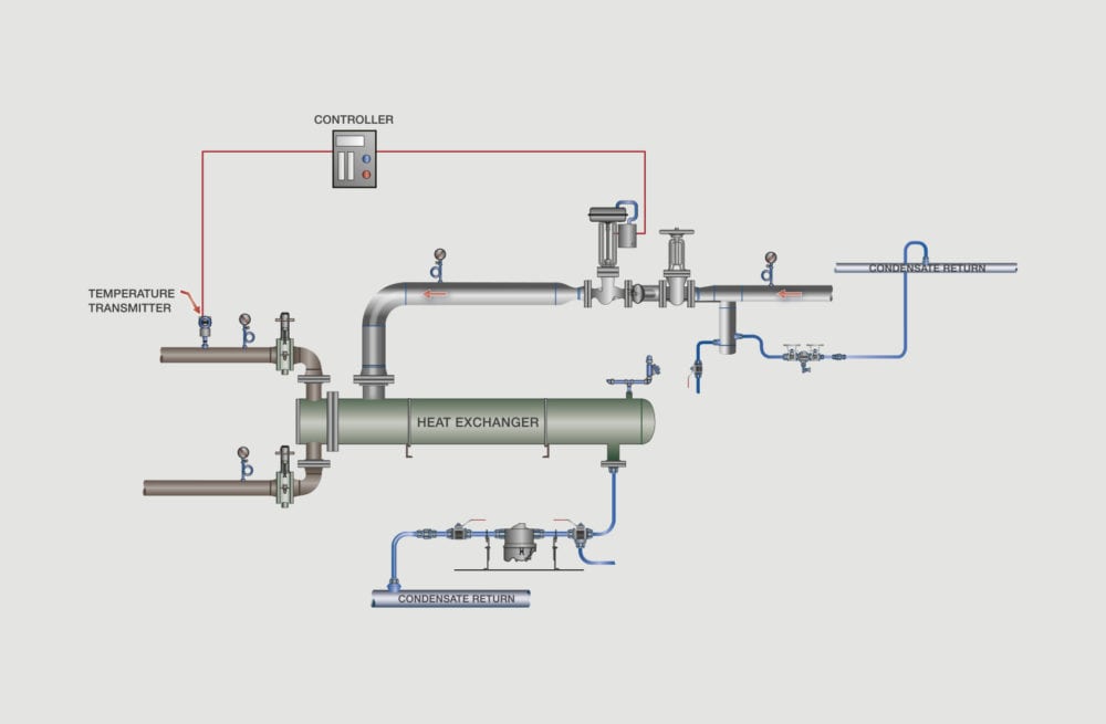
5. HEAT TRANSFER FEEDBACK CONTROL
One of the simplest and most common control scheme used in heat transfer is simple feedback control, shown in Figure No. 6. The control scheme does not account for any upsets, disturbances, or unknown factors that might occur in the system and affect the heat transfer process.

Figure 6: Heat Exchanger Feed Back Control
6. HEAT TRANSFER FEED-FORWARD CONTROL
The feed-forward control scheme uses feedback to control temperature of the process fluid and measures steam pressure on the heat exchanger as the feed-forward signal. A disturbance or change in process immediately causes a pressure drop to occur in the heat transfer due to the collapsing of the steam. The steam pressure feed-forward anticipates a process fluid temperature change prior to an actual temperature change measurement. The steam pressure feed forward control allows for the anticipation of process changes. See Figure No. 7.

Figure 7: Heat Exchanger with Feed-Forward and Feed-Back Control
7. HEAT TRANSFER FEEDBACK, FEEDFORWARD, CASCADE CONTROL
As Figure 8, shows, the control system in heat transfer applications an have feedback (temperature), feed-forward (steam pressure), and cascade (process fluid flow) into the control scheme. Using all possible variables in the heat transfer control can provide the highest degree of accuracy.
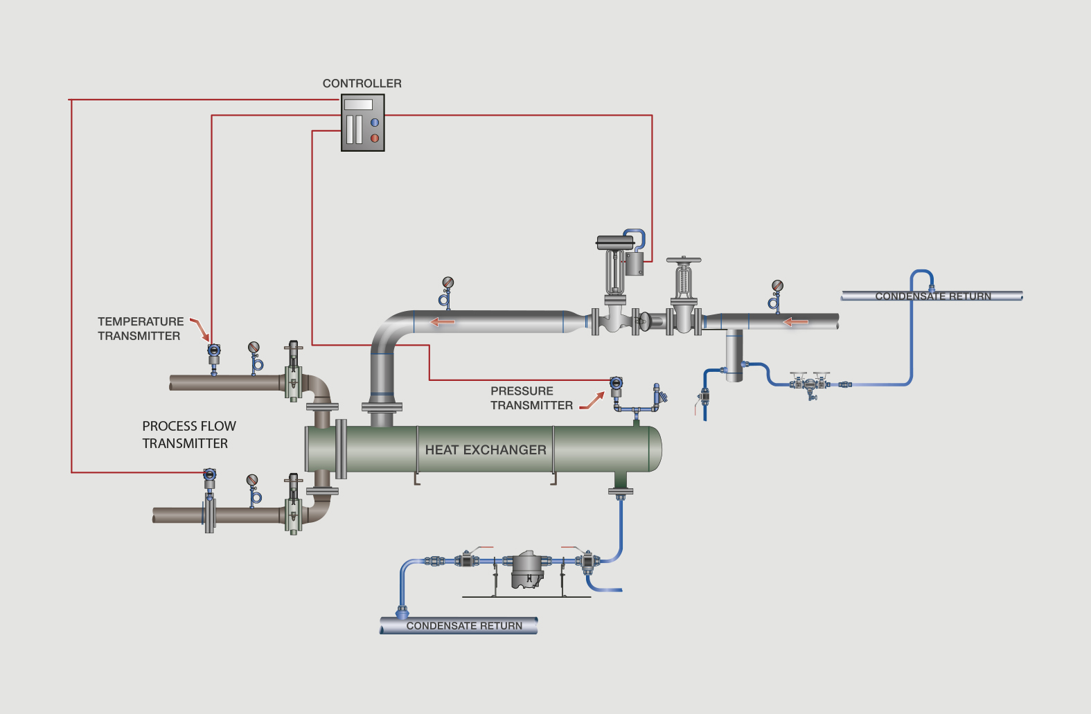
Figure 8: Three Element Process Control
8. FEEDBACK CONDENSATE CONTROL
The condensate feedback control scheme is used in condensate removal and is typically a simple level transmitter, controller, and control valve. This system is used on a heat transfer application, as shown in Figure 9.
In process flow operations where condensate flow rates are 8,000 lbs./hr. or higher, steam traps are not recommended. The recommendation is to use a condensate level transmitter, controller, and control valve with a feedback control scheme. The feedback control scheme provides the ability to remove the condensate from the heat transfer unit on a continuous basis. At high condensate flow rates, a control valve provides a high degree of accuracy, reliability and control in the removal of condensate from heat transfer.

Figure 9: Condensate Control
9. CONTROL VS. COST
The ultimate process control scheme is one that provides the system the most information possible, but to accomplish this goal, there is also a cost factor that must be evaluated. The more information being provided to the control scheme, the greater the cost for the field devices, and the more complex the controller, control strategy, wiring, and other additional components. Therefore, the user must understand that there is a cost justification to consider in identifying the correct control scheme for the process application.
CONCLUSIONS
Control strategies, when evaluated from basic inputs and outputs, are simple and straightforward. Control schemes should be determined based on the control accuracy necessary to meet the production requirements.
RECOMMENDATIONS
1) Outline your objectives and goals clearly before starting the selection process;
2) Select the correct control scheme for the process; and
3) Select the proper equipment for the application.


