Steam Valve Inspection and Testing – Best Practice No. 5
Do you want this article in PDF format? Download it here:
Download a PDFBEST PRACTICE NO. 5
STEAM VALVE TESTING PROCEDURES
Steam valves installed in plants create a perplexing problem: determining whether the valve has internal leakage. Internal steam valve leakage is one of the most difficult failures to analyze and costs plants millions of dollars a year.
It is very difficult, if not impossible, to determine whether a steam valve is leaking by studying its body temperature profile. The most reliable test method for internal steam leakage is using ultrasound at high frequencies above 25 kHz. Every test method has good and a few not-so-good attributes, but high-frequency ultrasound has proven to be an easy and accurate test method in 98% of applications.
This chapter will explain proper test methods with the goals of eliminating outside influences that can affect accurate ultrasound testing and improving the accuracy of test results.
1. STEAM VALVE INSTALLATIONS
There are several types of steam valve installations in industrial steam systems, but the majority of the steam valves are in three major areas:
- steam isolation valve applications,
- steam warm-up valve applications, and
- steam control valve applications.
2. HIGH-FREQUENCY ULTRASOUND
Steam leakage will result in a velocity flow (turbulence) passing across a valve seat that is in a failure mode and not providing the required shutoff. The leakage will generate a tremendous amount of high-frequency ultrasound. If the valve has internal leakage, it will contact the outside surface of the valve body and piping, resulting in ultrasound readings that will allow the testing person to draw the correct conclusion.
3. TESTING METHOD
The required testing points on the piping, upstream and downstream of the valve, will indicate whether there is competing ultrasound from sources other than the valve to be tested. If competing ultrasound is found upstream and downstream, then the competing ultrasound will need to be tuned out. The valve body test point is downstream of the valve mechanism (ball, plug, cage, butterfly, etc.) and valve seat area.
The distance between testing points upstream and downstream on the piping will depend on the valve/piping size, but as a general guideline, the first test point away should be 10” from the valve, and the second should be 24”. These dimensions can be altered, depending on the piping configuration and sizing.

Figure 1: Testing Points
4. STEAM ISOLATION VALVES
Steam isolation valves are used in the plant to isolate different segments of the steam system for different reasons. Internal leakage will prevent the steam system from being isolated and possibly lead to a total plant shutdown. Also, personnel need to determine which isolation valves are leaking before the plant outage and set a road map for repair.
4.1 Steam Isolation Valve Test Example 1
The higher the decibel reading, the higher the degree of leakage. The ultrasound reading at the outlet of the valve seat should be equal to or less than the readings upstream and downstream of the valve. In the example below, the valve was determined not to be leaking.
Figure 2: Main Valve Test with Equal Readings
4.2 Steam Isolation Valve Test Example 2
Figure 3 shows a high decibel reading at the outlet of the valve seat area, indicating that the valve is leaking steam.

Figure 3: Main Valve Leaking
4.3. Steam Isolation Valve Test Example 3
Figure 3 has a higher decibel reading, indicating that the ultrasound is coming from downstream of the valve in the piping system.

Figure 4: Downstream Ultrasound
5. BYPASS VALVES
Use the same procedures that we outlined to test bypass valves, as shown in Figure 4.
Figure 5: Testing Bypass Valves
6. CONTROL VALVES
There are two ways to test a control valve:
- checking the steam control valve for leakage, and
- determining the breakaway point or flow on a steam control valve at its opening.
The first method uses the same techniques as testing steam isolation valves and bypass valves for leaks. With the valve in the off position, test each point for leaks.

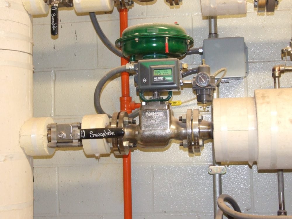
Figure 6: Control Valve Testing
The second test is used to determine the opening of a control valve where actual flow starts to occur, or the breakaway point. It follows the same procedures used to determine an internal leak, but as the tester starts to apply an input control signal (4-20 ma or 3-15 psig), it can be determine the degree of the control signal has to be applied before the valve will be opened to allow flow (steam) to the process. See Figure 6.
When setting up a control system, consider the breakaway point or steam flowing point through the valve. The steam flow may not occur until a 4.3 or higher (ma) signal is provided to the valve, which will affect the control PID function.

Figure 7: Steam Process Control Valve Testing


