No. 49 – Steam Process Control
Do you want this article in PDF format? Download it here:
Download a PDFThe technical paper Steam System Process Control provides a basic understanding of the different process control schemes used in a typical steam system. The technical paper is just an overview of the fundamentals; the reader should be aware that more in-depth knowledge is required to get the ultimate process control solution. The process control schemes that will be reviewed are:
- I. Feedback
- II. Feed-forward
- III. Backpressure
- IV. Ratio
- V. Cascade
- VI. Differential

Figure 1: Steam Process Control System
A few of the process control systems will have one or more of the above schemes to achieve the final process control solution. The applications of the various control schemes are detailed in the typical application examples defined in the best practice technical paper.
The above steam system process control schemes can be applied to the following generic applications:
- Temperature
- Felow
- Level
- RPressure
In any control scheme that is applied, the user must define three elements for the control process: the process variable, the controller, and the output control signal.
I. Process variable (sensing device)
- Flow transmitter
- Level transmitter
- Pressure transmitter
- Differential transmitter
- Temperature transmitter
II. Controller
- Self-contained
- Proportional and integral (PI)
- Proportional, integral, and derivative (PID)
III. Output control signal (final controlling mechanism)
- Control valve
- Actuator
- Another device
The best practice will focus on control valves, which are used in the majority of applications as the final control element. The control valve has several classifications.
I. Regulating design valve
- Self-contained
- External pilot operated
In any process control selection, it is important to understand the advantages and disadvantages of each selection.
Rangeability:
The ratio of the maximum controllable steam flow to the minimum controllable steam flow. Example; an open steam control valve (100%) with a rangeability of 50 to 1 and with a total steam flow capacity of 1,000 lbs./hr. will control steam flow accurately down as low as 20 lbs./hr. For this example; the steam control valve would not be controllable or have a stable flow at 15 lbs./hr.
Turndown:
It extremely important to understand turndown, which is the ratio between maximum usable flow and the minimum controllable flow; it is usually less than the rangeability. Example; 1,000 lbs./hr. steam requirement for the steam control valve has been applied for the application, it might turn out that the most steam flow the application would ever need through the control valve is 680 lbs./hr. Since the minimum controllable steam flow is 20 lbs./hr., the required turndown for the control valve is 34 to 1. In comparing rangeability and turndown, we may say that rangeability is a measure of the predicted stability of the control valve, and turndown is a measure of the actual stability of the valve.
Valve Turndown Requirements
- 20:1 Regulator
- 30:1 Globe valve
- 40:1 Cage control valve
- 70:1 V-Ball valve
Symbol Definitions
- PT = Pressure transmitter
- FT = Flow transmitter
- TT = Temperature transmitter
- CT = Controller
- RA = Ratio
- CS = Cascade
Feedback Control
One of the simplest process control schemes used in steam applications is the feedback control scheme (shown in Figure 2). The advantage of the feedback control scheme is that it is the simplest. Its primary disadvantage is that it depends on a single transmitter sensing a change in flow, pressure, or level to provide the response back to the controller or valve. In addition, this control scheme does not take into consideration any of the other variables in the process.

Figure 2. Feedback Control
Feedback Control (Backpressure application)
Feedback control for a steam system backpressure control scheme utilizes another parameter to provide the controller with information on process changes, as shown in Figure 3.
Backpressure control is used to maintain inlet steam pressure above a predetermined set point. Pressure transmitters are located on the inlet and outlet piping that will notify the controller that changes are occurring. Consequently, backpressure control is used in conjunction with feedback control. The most common application for a feedback control in a steam system is the elimination of instant high steam flow demand from a process that will affect the boiler plant operation.
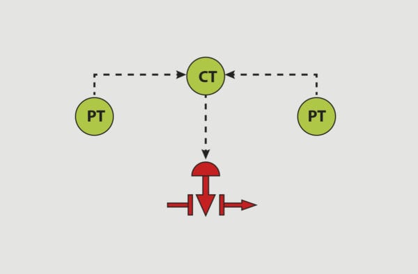
Figure 3. Feedback for a Backpressure Application
Feed-Forward Control
Feed-forward control uses a secondary input from another variable to assist or provide the controller with the knowledge that various changes are occurring in the process, as shown in Figure 4. Steam flow measurement in pressure-reducing applications adds instant identification that a change in downstream requirements is occurring. The steam flow measurement allows the controller to make corrective actions before a significant temperature or steam pressure change has occurred.

Figure 4: Feed-Forward Control
Consequently, feed-forward control is used in conjunction with feedback control. The feedback loop is used to maintain set point control, and feed-forward is used to compensate for any errors and unmeasured disturbances. One of the most common applications is a pressure transmitter used on a shell and tube heat exchanger to sense and feedforward a change in steam pressure. The steam pressure change on the shell side is the first indication that the temperature (process variable) will change in a very short period of time.
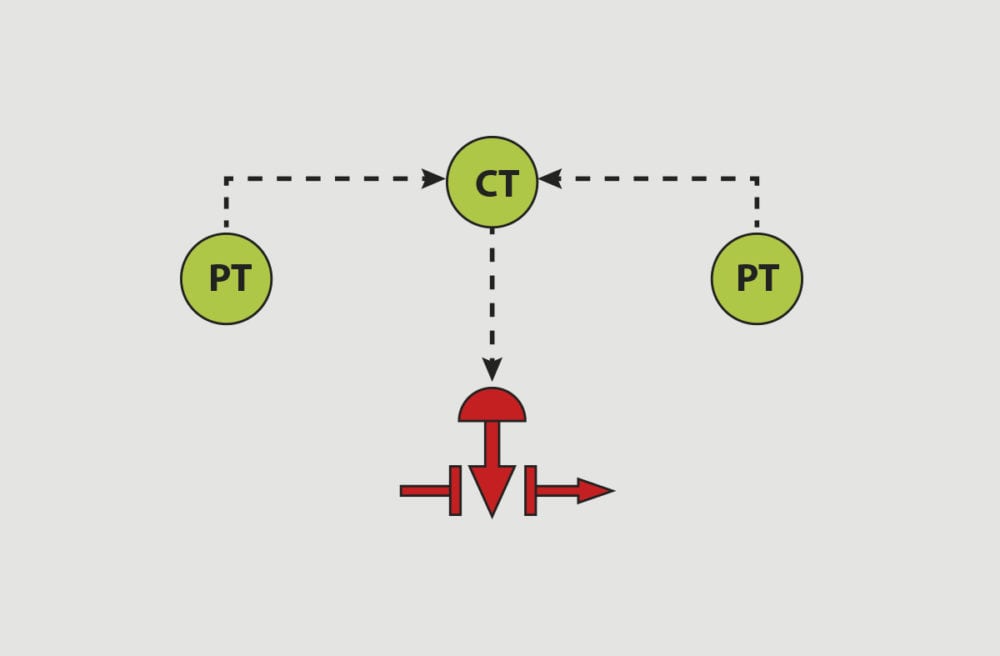
Ratio Control
Ratio control is a feedback control scheme that has two sets of output variables, which the controller calculates two outputs to the final control elements. The object of a ratio control scheme is to keep the ratio of two output variables at different values depending on the final desired objective of the control system. As Figure 5 indicates, in a pressure control system, the control output to the different valves is a ratio depending on the percentage of travel (0-100%) and the pressure transmitter. This type of control scheme is applied when two or more control valves are used in a pressure-reducing application. The control scheme is also use for high varying steam flow demands for a process application. The ratio control allows for a high turndown when using two final control valves.

Figure 5. Ratio Control
Cascade Control
Cascade control, shown in Figure 6, is widely used within steam process industries. The conventional cascade scheme has two distinct functions with two control loops. Cascade control is used to improve the response of the single feedback strategy. A heat exchanger’s varying process flow will have different steam demand requirements depending on the process fluid flow. Cascade control understands the requirements and adjusts the output to the control valve according to the process flow from the process flow meter. The main objective is to achieve the desired output temperature of the process, which is the lead process variable. The idea is similar to that of the feed-forward control scheme.

Figure 6: Cascade Control
Differential Control
Differential control, shown in Figure 7, is used typically on rotating cylinder dryers because differential pressure is required across the siphoning joint to assist in evacuating the condensate. The use of rotating cylinders is the only process where gravity drainage of condensate is not possible. Therefore, using differential control identifies the parameters of inlet and outlet process pressures and maintains a lower outlet steam pressure, thus achieving the differential. A inlet pressure and a outlet pressure measurement is required to achieve differential control. Typically, there are two control valves, one control valve for the steam supply and one control valve to control the flash tank pressure, which condensate from the rotating dryer is discharging into the flash tank.
Differential control is also used in other limited heat transfer applications.

Figure 7: Differential Control
Control Actions
The controller’s output to the final control element (valve or actuator) is accomplished by various methods.
- On/off
- Simplest
- Least accurate
- PI (proportional and integral)
- Medium cost factor
- Medium accuracy
- PID (proportional, integral, and derivative)
- Highest cost
- Highest accuracy
On/Off Control
Control schemes using a feedback control parameter can use on/off control. On/off control is the simplest control scheme, but it has the highest degree of inaccuracy. The controller has set points with high and low control action points, similar to a home air conditioning or heating system. The thermostat has a desired set point, and the system is operated between two temperature points (on/off).
If a desired outlet temperature is 180°F, the on/off control would activate the steam valve to heat the product to 185°F. At 185°F, the steam valve would be deactivated, and this would allow the process to cool down to 175°F (the lower set point). The steam would be activated and deactivated between the high and low process set points.
PI Control
PI control will use a proportional (proportional to the difference between a set point and a process variable) and integral (a totalizing function) algorithm, which provides a continuous control process output to meet the desired set point. This is similar to a light dimmer switch versus an on/off light switch. The dimmer mechanism provides a light variable from off to full brightness or anywhere in between. Similarly, PI controls the steam flow from zero to full flow or anywhere in between on a continuous basis.
PID Control
PID control has proportional, integral, and derivative algorithms available for use to maintain the set point of the process. Steam applications use the proportional and integral part of the PID. The derivative algorithm is used very seldom and then only by someone very experienced in control algorithms. If the heat transfer equipment, control valve, and the controller are properly selected, then proportional and integral are the only parameters required to maintain a highly accurate process result.


