No. 44 – Steam Thermocompressor Systems
Do you want this article in PDF format? Download it here:
Download a PDF1. THERMOCOMPRESSOR
A thermocompressor is a device that uses high-pressure steam as a motive force to entrain a lower-pressure steam and discharges the mixture at an intermediate steam pressure. Applying the device correctly into the steam and condensate system can save the plant a tremendous amount of energy and reduce emissions. The technology has been used for many years in several industries. Today, with the cost of fuel rising and the immediate need not to vent the system to the atmosphere, steam plants are reviewing the operation and application of steam thermocompressor technology to recover low-pressure steam that is not required for use in the process plant. Many industrial plants are looking at the different steam thermocompressing applications to improve the steam system balance.

Figure 1: Thermocompressor Flash Tank
The thermocompressing units are simple and versatile and can be applied in many different steam process applications. The units have few moving parts and have a relatively low cost for implementation into the steam system. Thermocompressors typically used in steam operations are either the fixed nozzle type with a throttling control valve in the motive steam supply line, the type with an automatically controlled spindle, or the type with a variable orifice design.
2. CONSTRUCTION AND OPERATION
Thermocompressors and ejectors operate on the same thermodynamic and physical principles. One common principle is that some of the energy contained in highpressure steam can be transferred to a lower-pressure vapor or gas to produce a mixed discharge stream of intermediate pressure. The only difference is the objective. The components of a thermocompressor are as follows:

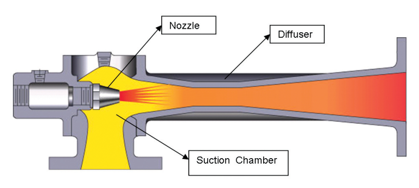
Figure 2: Thermocompressor
- Body
- Diffuser
- Nozzle
- Spindle
- Actuator to move the internal spindle
A thermocompressor is a device used to recover the latent heat content of the low-pressure suction steam to produce an intermediate steam pressure for use in the industrial plant.
An ejector is a unit used to create a vacuum in a process application. The ejector operation will typically contain noncondensable gases, which makes it very difficult to recover the heat energy from the suction vapor.
The motive steam leaves the nozzle at high velocity (1,500 to 2,500 ft./s). High-pressure motive steam is delivered at a very high velocity through a converging diverging nozzle, where it comes into contact with the low-pressure steam, resulting in entrainment and mixing.
High-pressure inlet motive steam is expanded in the nozzle to the suction chamber, where the pressure energy is converted to velocity energy. The mixed jet flow stream is then forced through a diffuser, where the kinetic energy is converted into potential energy. Steam compression is achieved through converting potential or pressure energy into kinetic energy and then back to pressure energy. The name thermocompressor is derived from the process of using thermal energy or the enthalpy of steam to achieve compression.
A thermocompressor requires engineering to balance the steam flow streams, including a determination of the correct steam flow and steam pressure of the motive steam, suction, and intermediate steam. An incorrect balance of the steam flows could result in choke flow conditions, and an increase in motive steam could lower the suction steam flow.
3. PERFORMANCE
The performance of a thermocompressor consists of two types, critical and noncritical, based on the compression ratio. The compression ratio is defined as the discharge absolute steam pressure divided by the suction absolute steam pressure: ratio = P2/Ps (absolute units). If the steam velocity in the diffuser throat is sonic, the design is defined as critical. Sonic velocity exists when the compression ratio (discharge pressure/suction pressure) is equal to or greater than 1.8 to 1. The value of this ratio changes as a function of the ratio of the specific heat of the motive and suction steam.
The performance of a steam thermocompressor is generally evaluated for several anticipated operating conditions, but normally a minimum and maximum operating point are sufficient. To properly size the unit, the thermocompressor requires the following design data:
- Motive steam pressure
- Motive steam temperature
- Suction steam pressure
- Suction steam flow
- Discharge steam pressure
The calculations are then made on maximum-minimum conditions, and a thermocompressor design is determined.
At higher motive steam pressures, the entrainment ratio tends to be lower for the same compression ratio. Typically, thermocompressors are feasible for low compression ratios (2.5), while for higher compression ratios, the complete steam balance must be evaluated to arrive at a suitable solution due to the increased entrainment ratio requirement. Typical entrainment ratios vary between 1.5 and 3 and depend on expansion as well as compression ratios.
4. STEAM THERMOCOMPRESSING APPLICATIONS
There are many different applications for steam thermocompressor systems in today’s industrial plant operations.
4.1. Thermocompressing Flash Tank Systems
The thermocompressor uses high-pressure motive steam to remove low-pressure flash steam from the flash tank and deliver it to an intermediate steam pressure. It uses a very simple control loop to consume low-pressure steam and provide a more useful steam pressure for the processes.

Figure 3: Thermocompressor off a Flash Tank Arrangement
4.2. Recirculating Loop Thermocompressor System
The recirculating loop system consumes the flash steam off the condensate discharge of the process application, which can be of any process type (rotating dryer, heat exchanger, reboiler, process air unit, etc.). The thermocompressor using high-pressure steam as the motive force consumes the flash steam off the flash tank and provides a usable steam-pressure back to the inlet of the process steam supply. A make-up valve provides the additional steam to maintain the process requirements for steam energy.

Figure 4: Recirculating Loop Thermocompressor System
The recirculating loop system is a very efficient method for steam balancing a process application.
4.3. Steam Balancing System
The steam balancing system thermocompressor system uses unnecessary low-pressure steam by using the higher- pressure steam as the motive force and developing an intermediate steam pressure. This prevents the venting of low-pressure steam that has no applications in the plant’s processes.

Figure 5: Steam Balancing System


