Testing Steam Trap Stations – Best Practice No. 33
Do you want this article in PDF format? Download it here:
Download a PDFBEST PRACTICE NO. 33
TESTING STEAM TRAP STATIONS
When it comes to testing steam traps, a frequently asked question is, “what is the best method?” The true answer is to use all of the technologies available today. No single test method provides the best results all of the time for the variety of steam traps in the marketplace. Therefore, all tools available in the marketplace should be implemented and used where appropriate. So, what are these tools? They can be segmented into three (3) categories:
- Visual
- Temperature
- Ultrasound
Becoming proficient with these tools is like riding a bicycle – the more you ride the bicycle, the better you become. Practice and gaining the knowledge of the methods is the key to successfully using the different devices.
1. Visual Methods
The use of a testing-tee valve arrangement, testing-valve combination, or an inline sight glass for reviewing the steam trap discharging to the atmosphere is a very effective way of testing steam traps. This visual method can accurately determine the following conditions:
- Blow-through steam or a failed open condition
- Severe steam leakage
- Under-sizing

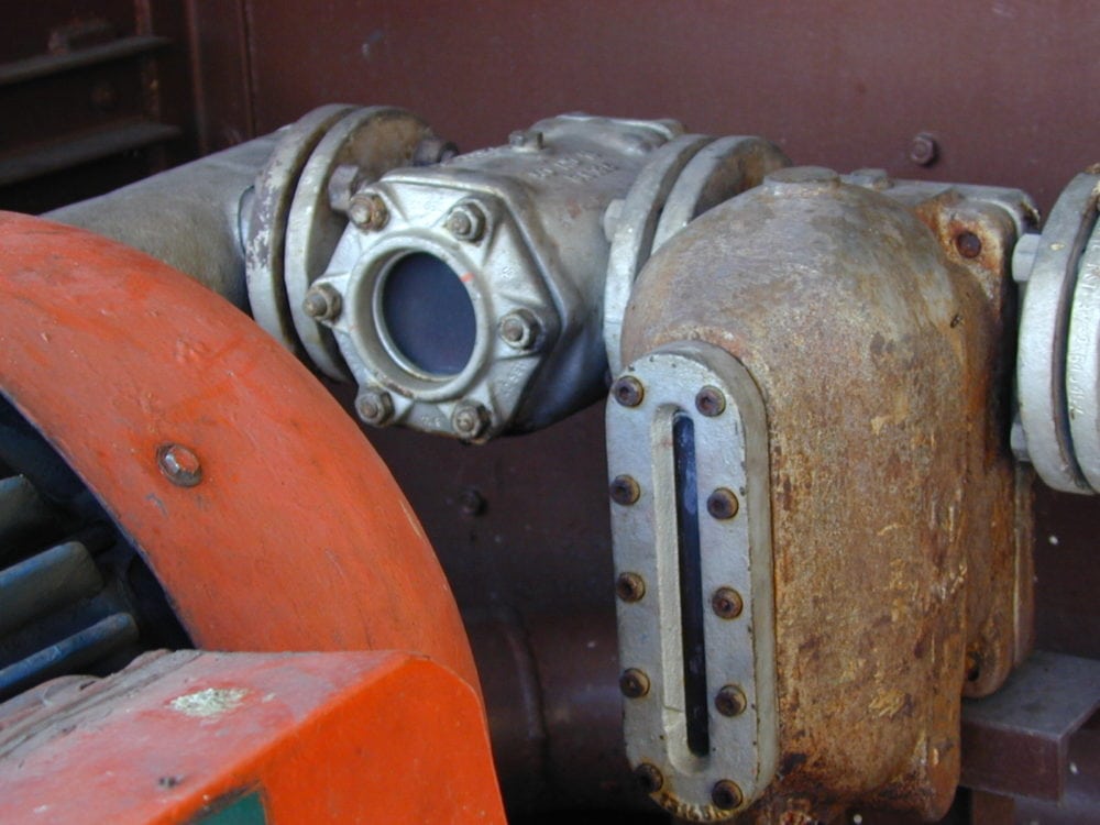
Figure 1: Visual Indicator on a Steam Trap
There are some negatives to any testing method and the visual method is no exception. The inspector must understand the concept of flash steam and become aware of difference between flash steam and blow through steam. There are safety concerns due to the release of hot steam to atmosphere during the testing phase. Finally, there is a small additional cost associated with installing the components that permit online testing.

Figure 2: Steam Trap Test Valve
2. Temperature Testing Equipment
Temperature measurement equipment must be an integral part of a steam system testing program. It is by no means the only piece of equipment that should be utilized, but can help provide information that would otherwise not be available. Understanding the limitation and capabilities of your temperature measurement equipment will only enhance its usefulness. The pressure/temperature relationship of steam makes temperature measurement extremely helpful in establishing existing steam system pressures.
Infrared testing devices will detect the temperature of the steam line ahead of the trap and at the discharge of the steam trap, but it is only estimated the existing steam pressure. The testing person must be knowledgeable of steam pressures before and condensate line pressures after the steam trap to understand the steam trap performance. The inlet temperature provides insight into the saturated steam pressure at the inlet of the steam trap. The outlet temperature of the steam trap will correspond to the condensate return line pressure or back pressure existing in the condensate line.
At best, results using temperature indication is only accurate about 44% of the time. Low steam pressure systems are practically impossible to test using temperature methods. The primary role of infrared devices is to provide a surface temperature during the testing procedure and therefore a pressure reading at any point in the system.
Types of Temperature Measurement Devices
There are basically two types of temperature measuring devices on the market today: (1) contact and (2) non-contact.
Contact Temperature Devices
Contact temperature measuring devices require time for the temperature at the point of contact to reach the same temperature as the object being tested. Depending on the surface conditions, this may not be an acceptable method of temperature measurement.
When measuring surface temperature of solid materials, the area where the readings will be taken may need some surface preparation. For instance, large build-up of residue on a surface will cause the reading to be lower than the actual surface temperature. One other factor that may affect the accuracy of the reading will be the integrity of contact point on the device.
Non-Contact Temperature Devices
Non-contact temperature devices measure the surface temperature of a given piece of an object utilizing radiated infrared energy. Infrared devices provide an instantaneous temperature measurement, typically without any surface preparation. However, for highly reflective surfaces, the surface should be prepared such that the infrared energy can be absorbed and detected by the instrument. Infrared energy is sensed by optics/lenses that are sensitive to the non-visible portion of the light wave band. These types of devices provide varying degrees of accuracy depending on the following criteria:

Figure 3: Infra-red Temperature Unit
- Quality of optics
- Spot or target diameter
- Range
- Emissivity compensation for varying surface emissivity
- Ambient Temperature

Figure 4: Field Testing with Infra-red
The best results are obtained when a few basic concepts about infrared heat radiation are understood. All objects radiate infrared energy to some degree. This energy radiates in all directions much like light from a light bulb. The infrared thermometer has a lens that collects the radiated energy and focuses it on an infrared detector. The detector responds by producing a voltage signal, which is proportional to the amount of energy received. This voltage signal is correlated to a given temperature, which is displayed on a meter or LED display.
It is important to realize that not all infrared temperature measurement equipment are created equal. The main variable that affects how well a unit will work for a given application is its ability to adjust for different emissivity.
What Is Emissivity?
Some objects reflect infrared energy as well as radiate it. Shiny or highly polished surfaces will reflect more infrared energy than dull surfaces. A factor called emissivity is the ratio of radiated energy of an object compared to radiation of a black body. The higher the emissivity numbers, the smaller the portion of heat energy reflected and the more accurate the reading. Infrared sensors are accurate for emitted energy. Reflected energy requires adjustment.
Infrared rays follow the same laws as visible light. Some of the light will be absorbed on a given surface and part of it will be reflected. Black is the optimum color that absorbs light, so we can assume that there will be no reflected infrared energy. The use of the term “emissivity” is an attempt to give some idea as to what portion of the infrared is reflected and how much is radiated. Emissivity will be noted as a number between 0.0 and 1.0.
Most surfaces encountered in the steam world will have an emissivity between 0.8 and 1.0. This range of emissivity has little reflected energy – no more than a one-degree difference in readings. When selecting infrared scanning equipment, it is necessary to decide the degree of accuracy needed and then select equipment accordingly.
Checking For Unknown Emissivity
Some infrared temperature measurement devices have features that enable you to adjust emissivity. Charts that accompany such units guide the user with selection for a given surface. Equipment without this feature can be used for measurement of objects with varying emissivity, by using a simple method of manual control.
Ultrasonic Testing Equipment
Ultrasonic testing equipment provides the most versatile and accurate steam system diagnostics tool available today. The ultrasonic unit allows the operator to hear sounds unable to be heard by the human ear. This type of equipment receives a high frequency signal (typically between 20 – 100 KHz) and heterodynes the signal providing an audible sound for the operator to hear with the aid of headphones. Typical applications for performance testing include the following components:
- Steam traps
- Steam leaks
- Heat exchangers
- Steam valves

Figure 5: High Frequency Ultrasound Unit
Ultrasonic steam trap testing is the final test method to be used in the steam trap testing program for detecting faulty steam traps. The operator utilizes the stethoscope module to contact the discharge side of the steam trap, and has the ability to sense and detect even subtle changes in operational characteristics or malfunctions.
The sensitivity of most high frequency monitoring equipment allows the testing person to hear not only completely failed steam traps (blowing steam), but even leaking steam from a steam trap in operation. This test method provides the earliest signal of steam trap wear and is used as a predictive tool for steam trap monitoring. Ultrasonic testing permits the testing person to hear the internal operation of the steam trap; so the effectiveness of the steam trap operation can be determined.

Figure 6: High Frequency Ultrasonic Unit Field Testing
Standard Operating Procedure for Testing Steam Traps
Visual
The steam trap must be visually inspected for the following conditions:
- Proper Installation
- Proper Flow
- Level
- Trapset components in place
- Type of steam trap
- On/off or continuous flow
- Collect necessary information for input into the trap database
- Model
- Size
- Trap ID number
- Manufacturer
- Type
- Location
Temperature
Temperature measurements must be taken upstream and downstream to determine the inlet steam pressure and the condensate line back pressure. Temperature differential across the steam trap is calculated once the inlet and outlet pressures are determined. There is no single correct temperature differential across a steam trap that verifies a properly operating steam trap or a steam trap that is failed.
- Inlet temperature – steam/condensate line to the inlet steam trap
- The temperature to the inlet of the steam consumer (equipment) should be measured and compared to the inlet of the steam trap. These temperatures should be close in temperature measurement (± 20° F)
- Outlet temperature – condensate line downstream of the steam trap
- Determine the back pressure that is present in the condensate line.
Ultrasound Testing
a. Sensitivity Settings for Ultrasound
(Scale = 0 – 100%)
b. Selecting Testing Procedure
Testing steam traps is simplified when the manufacturer classifies the steam traps as follows:
- On/Off operation
- Continuous flow
c. Comparison Method
When testing a steam trap and the testing person is not sure of the steam trap performance, then a comparison method should be used. The comparison method is accomplished by taking three individual ultrasonic readings.
- Upstream
- Discharge side of the steam trap orifice
- Downstream
See the figure below for recommendation on the spots to choose.

Figure 7: Testing Reference Points
Testing
Place the stethoscope at the discharge side of the orifice in the steam trap. The highest level ultrasound is generated at this point.
Pull the ultrasound trigger and the take the measurements.
Conclusion
Testing steam trap stations can be very easy if the plant provides the correct equipment, training and commitment to the Steam System Management Program.


