No. 31 – Visual Indication Of Condensate Evacuation
Do you want this article in PDF format? Download it here:
Download a PDFBEST PRACTICE NO. 31
VISUAL INDICATION OF CONDENSATE EVACUTION
READ FULL PDF TECHNICAL PAPER – CLICK HERE
All steam system plant personnel seem to share two major concerns: (1) Is condensate being properly evacuated from the process, and (2) is steam being prohibited from blowing through the condensate drainage devices (steam trap stations, control valves, etc.) so it doesn’t waste energy and cause component failure?
Plant personnel can employ something called “visual indication” to answer both of the above questions regarding condensate drainage. Used in certain process plants for 85 years, visual indication remains the most-successful way to determine proper condensate evacuation.
Test valves and sight glasses or sight windows (Figure 1) provide simple, reliable ways to check flow, identify performance, manually measure flow, and conduct line sampling in steam and condensate systems. More importantly, test valves and sight glasses or windows allow plant personnel to verify existing conditions within a closed condensate piping system.

Figure 1: Two Types of Visual Indication
Visual Indicators
As shown in Figures 1 and 2, these visual types of devices allow plant personnel to visually check for proper condensate drainage from the heat transfer process. This means that most any person within the plant is qualified to determine if the condensate drainage and steam trap station is performing to specifications.
These simple devices provide benefits that far outweigh the cost of purchase and installation.

Figure 2: Inline Flow Indicator
Test Valves
Test valves can be fabricated in the field using a standard set of valves or purchased as a complete unit. The most-desirable operation comes from units that are purchased as an “integrated test valve assembly.” If the steam trap is operating properly, condensate will flow from the test valve vent. If a continuous flow of steam comes out of the test valve vent, the steam trap is not functioning properly. If nothing comes out of the test valve vent, there may be blockage upstream of the vent, or the integrated strainer may need to be cleaned.

Figure 3: Steam Trap/Sight Glass
Steam Traps with Visual Indicators
Steam traps can be purchased with visual indicators in the body of the steam trap, as shown in Figure 3. Using this type of flow indication yields a more compact installation.
Best Practice
- To verify proper condensate drainage, visual indicators need to installed and used on all process application and critical condensate drainage locations.

Figure 4: Typical Installation of Flow Indicators
2. Visual indicators can be used on any steam trap station application.
3. Visual indicators mounted on the condensate outlet of the process and before the steam trap station or control valves provide the truest visual indication of condensate drainage and heat transfer steam/ condensate performance.
4. If using a test valve, position the valve vent so it points away from operating personnel.

Figure 5: Flow Indicators Installed

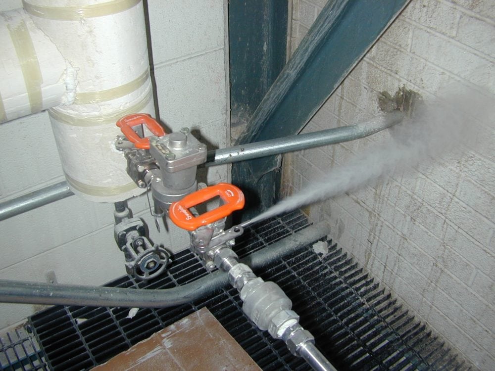
Figure 6: Test Valve in Operation
5. Steam valves must be of Class VI (FCI standard) internal shut-off leak standard. Test valve failures in the field are typically test valves that do not meet this standard.


