No. 29 – Steam Tracing Installation
Do you want this article in PDF format? Download it here:
Download a PDF1. STEAM TRACING DESIGN AND INSTALLATION CONSIDERATIONS
When designing a modern steam tracing system, the plant needs to consider a number of design and installation factors to ensure an efficient and reliable operation.
1.1. Process Temperature
If the process fluid temperatures are to remain constant in the process lines, then the amount of heat energy that has to be added must be equal to the amount of heat energy being lost from the process fluid. The lost energy can be from insulation, pipe hangers, pumps, valves, etc. The energy measurement is usually measured in watts per meter (W/m) or Btus per hour per foot of pipe (Btu/hr.-ft.). Correctly matching the steam tracer type with a heat output that will closely balance the heat loss from the process will improve the system’s efficiency.

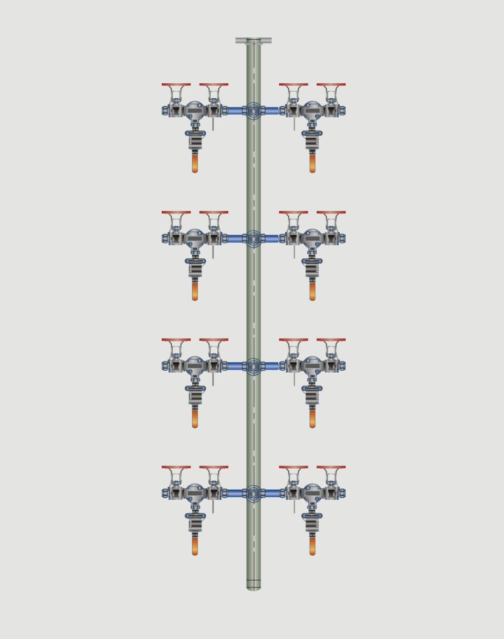
Figure 1: Four Tracers Design
1.2. Process Evaluation Items
The plant must review and evaluate many different items to select the proper tracing system. These items include:
- startup time
- process temperatures (maximum and minimum),
- steam pressure available (maximum and minimum), and
- condensate recovery system (pressurized or not pressurized).
1.2.1. Startup Time
The highest energy demand occurs at startup, and the time allowed for startup will affect the steam flow requirements. The shorter the warmup time allowed, the higher the steam flow requirements. Also, the addition of more heat transfer surface area or higher steam pressures could be required.
It is important to work with the production area to evaluate the startup requirements to ensure you provide the proper steam flow requirements and the heat transfer surface area.
1.2.2. What Are the Process Temperature Requirements?
The process temperature will dictate selection of the materials and the components. The process temperatures will also dictate the steam pressures that the plant will have to use for the heating.
Use conduction-type tracers when process temperatures exceed 175°F. Bare convection tracers are used at lower temperatures, including freeze-protection applications.

Figure 2: Process Line

Figure 3: Supply Arrangement Figure 4: Tree Arrangement
1.2.3. How Long Is the Process Line?
Tracers are generally limited to 150 feet. For longer lengths, engineering is required. The plant should consider the steam header size; the pressure drop from fittings, valves, and bends; any increases in elevation; and return system pressures.
1.3. Supply and Condensate System Trees
Design and selection of the steam supply tree and the steam trap station tree are critical components for a successful operation. When considering tree arrangements versus nontree arrangements, keep in mind that engineering studies have shown that tree arrangements provide a more reliable steam and condensate operation than nontree arrangements. Tree arrangements are less likely to experience leakage problems, and their steam trap station reliability is higher. Tree arrangements provide maintenance and operation personnel the ability to quickly determine whether any problems are occurring in the system.
1.4. Selecting a Steam Trap Station
Select a proper steam trap station; do not just select a steam trap, which is only one component of the system.

Figure 5: Steam Trap Station Components
Steam Station Components:
A. Steam isolation valve
- Class IV or higher shutoff standard
- Class VI is recommended
B. Numbered tags for all components
C. Universal connector for the steam trap
D. Universal connector strainer
E. Blowdown valve for the strainer
F. 20 or 40 mesh
G. Steam trap
H. Test valve
- Isolation for the discharge side of the steam trap station
- Visual steam trap testing
- Class IV or higher shutoff standard
- Class VI is recommended
1.5. Required Steam Pressures
If the plant’s steam pressures are too high for the tracing application, then the plant will need to add a way to reduce the pressure in the steam system.
1.6. Piping or Tubing Material Selection
Materials selection is a factor in the ability to transfer the steam energy to the process system. Stainless steel is the preferred material for tracing applications, but stainless steel has a lower thermal conductivity rating. Industrial plants used copper tubing in previous years, but it will deteriorate over time, causing problems with fouling or plugging in the system and with returning the condensate to the boiler plant.
1.7. Insulation Type and the K Factor
The type of insulation and the K factor are very important. The highest energy losses are from the insulation. The K factor of the insulation will determine the degree of loss for the insulation.
1.8. Selecting a Condensate Return System
The steam tracing system typically modulates the steam pressure to the steam tracer system; therefore, the plant can use a pressurized condensate system to recover the condensate. The pressurized condensate system will have very high thermal steam cycle efficiency. Pressurized condensate systems operate continuously at a pressure above 15 psig, and the condensate return system is not vented to the atmosphere. The pressure in the condensate system is sustained by the dynamics of the system or a systematic control process loop.
Typical condensate systems operate with some backpressure due to condensate line undersizing and neglect of steam traps blowing steam into the condensate line. These items alone can cause pressure in the condensate system. A pressurized condensate system differs in that the condensate return pressure is systematically controlled to a predetermined set point, which is matched to the peak performance level of the process to achieve the highest steam thermal cycle efficiency.
1.9. Determining the Number of Required Tracers
If possible, the plant should try to limit the number of steam tracer lines to one for each process pipe. The tracer line should be located at the bottom of the pipe, as heat energy will rise. Adding more tracers will require additional connections to the supply and return header and the associated valve and fittings required for the connections. The number of tracers will depend on the amount of heat required and the size of the process pipe.

Figure 6: Double Tracers
1.10. Small Process Lines
If the process line is a smaller size (under 1”), then the use of preassembled tubing bundles can take most of the guesswork out of the design and engineering. In choosing tubing, the plant should consider the temperature requirements, steam pressures, ambient conditions, and level of temperature control.
In Figure 12, you can see examples of preassembled tubing. The tubing on the left side is for “light” steam tracing, or when lower temperatures are used. You can see that there is more insulation between the tracer and the process tube or tubes. The right half shows tubes that are considered “heavy” steam traced, and these are for use in higher temperatures. Note the proximity of the tracer and the process tube.

Figure 7: Tubing Bundles
1.11. Safety Considerations
The plant must also consider safety when employing steam tracers. All steam tracer lines above the pressure of 15 psig fall within the ASME B31.1 code; thus, all components used should meet the code requirements. All supply and discharge lines feeding the tracer system should be insulated for energy reasons and personnel protection.
1.12. Standardizing Materials and Designs
Materials and designs should be standardized where possible. Some of the items that will need to be specified include the following:
- valves (Class IV shutoff at a minimum),
- fittings,
- tubing size and material,
- insulation,
- gauges, and
- steam traps.
2. STEAM TRACING INSTALLATION CONSIDERATIONS
An efficient and reliable steam tracer system relies on the following design considerations:
- The steam supply for the tracer system should be connected at the top of the main steam header to ensure there is no condensate entrained in the steam supply. See Figure 8.
- Each tracer line should have its own steam supply isolation valve and steam trap station. See Figure 9.
- Condensate is drained from the steam tracer system through gravity; therefore, the plant should review the following items:
Figure 8: Steam Supply
a. Ensure there are no low spots in the tracer run.
b. Do not wrap the tracer around the process pipe. Figure 10 shows this common error. Condensate can and will build up in the low spots until it fills the tube, which will result in poor heating and possibly water hammer.
c. Steam tracer installation should flow from the highest elevation to the lowest.
d. If possible, slope the tracer to the steam trap station.

Figure 9: Tree Arrangement
4. Tracers should be installed on the bottom of the process pipe. Heat rises, and by installing the tracer on the bottom of the pipe, the plant will achieve greater efficiency.

Figure 10: Error: Wrapping Tracer Around Process Pipe
5. The correct support will prevent sagging on the steam tracer line and ensure the tracer line is in contact with the process pipe. Figure 12 depicts small sags, which induce air gaps that will greatly reduce the heat transfer capability.

Figure 11: Double Tracers
Figure 13 indicates the proper support for the tracing system.
6. The tracer line will expand and contract; therefore, the forces of expansion and contraction must be designed into the system. Using the common horizontal pipe loop will give the line the ability to accommodate the expansion.
7. The tubing material and fitting material should be the same.
8. Do not install tracing connections under the insulation. Install the connections at points that will allow the process equipment to be easily removed or repaired.

Figure 12: Improper Support for Tracing System
9. Tracer steam supply valves and steam trap stations should be marked and easy to identify. This will facilitate maintenance on the tracer lines because they will be easy to isolate.

Figure 13: Proper Support for Tracing System
10. Use preassembled steam and condensate return headers. These systems will typically have fewer connection points and will be designed to handle the steam loads.
11. Generally, do not use tracing with nonmetal or lined piping or vessels.
12. Minimize the number of connections to reduce the potential for leaks.
3. MAXIMIZING STEAM TRACER EFFICIENCY
Basic awareness of the steam tracer system will greatly influence the system’s overall efficiency. Do not break the system into components. If the plant considers overall design in conjunction with the rest of the steam system, it can make informed decisions.
One of the best ways to maximize steam tracer efficiency is to use steam that would otherwise be wasted: in other words, flash steam.
The return on the investment the plant makes in the equipment required to recover this flash steam is quickly paid back, typically within a year.
Another key point is to perform regular testing and maintenance on the tracing system. The plant should regularly check valves and steam trap stations to ensure they are operating correctly.


