No. 28 – Steam Tracing Overview
Do you want this article in PDF format? Download it here:
Download a PDF1. Introduction
Industrial plants require a method to keep the process fluids flowing during operation and to prevent critical components from freezing in low ambient temperature climates. In the early 1900s, the refining industry began using steam tracing systems to satisfy this need. At that time, efficiency and energy cost were not the major factors they are today, and earlier steam tracing methods were not very efficient. The standards for insulation, installation designs, materials, and maintenance were not economical and provided less than desirable results for the process conditions.
Steam tracing systems perform two very important functions in an industrial plant:

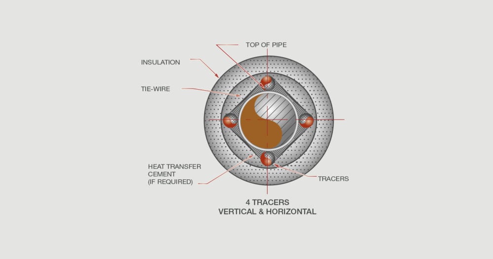
Figure 1: Steam Tracing System
- They replace heat loss from the process fluids in the system due to poor insulation or other components, thus keeping the process fluids flowing.
- They prevent any system from freezing in low ambient temperature climates.
The negative effects of poor design and installation can be catastrophic to reliability and production operation, which ends up costing the plant time and money. Therefore, steam tracing is a key component in maintaining a reliable production process operation.
Today’s steam tracing systems use the latest technology in components and design standards, thus making these systems very efficient and reliable. As with any steam component today, we expect no system failures within six years of operation. Using the medium- or high-pressure condensate return system designs provides a highly energy-efficient thermal cycle.
2. STEAM TRACING DESIGNS
2.1 Gut Line Systems
The gut steam trace line system has a center pipe or tube operating at some steam pressure, thus providing a large heat transfer surface to heat the fluid. The inner pipe or tube installation is difficult to properly support, and the supply and condensate line has to penetrate the process pipe’s outer wall. Expansion and contraction of the inner pipe or tube versus the process pipe also presents several problems that need to be resolved for proper operation. In most cases, inner tube or pipe failures are somewhat difficult or impossible to detect. In addition, maintaining the inner pipe or tube steam system is equally impossible.

Figure 2: Gut Line System
The negatives outweigh the positives in using the gut system; therefore, systems other than the gut system are usually found in the process world.
Advantages:
- Large heat-transfer surface area
Disadvantages:
- Difficult to install
- Almost impossible to detect any leaks
- Difficult to maintain
2.2 Jacket Pipe
If the process requires a high energy addition to ensure proper operation, the alternative to using a gut steam tracer is a jacket pipe system. In this system, the process pipe is encapsulated by a surrounding steam jacket. The jacket totally encapsulates the process piping, providing a very large heat transfer surface area to allow the high release of energy to the process. The steam jacket system can accommodate high steam pressures and temperatures. However, one limitation is the process convection coefficient.

Figure 3: Jacket Pipe System
As shown in Figure 3, several straight pipe spools with jackets can be connected with a common steam and condensate line, depending on the energy release quantity or steam flow requirements. The jacket system does contain concealed weld areas, and the plant should review all quality control procedures for the fabrication to ensure there are no weld failures. Weld failures can cause contamination either in the process or in the condensate drain system. Either type of failure can cause major problems for the plant.
Process valves and other components can be jacketed and connected in series with the jacket pipe steam and condensate system. Any series of condensate line connections that are installed should not have any rises in the condensate drainage system that can prevent gravity drainage from the system to the steam trap station.
Advantages:
- Large heat transfer surface area
- Easier to install than the gut steam tracing system
Disadvantages:
- High installation cost
- Concealed weld points and failure points are hard to detect
2.3 Bare Tube Tracing
Bare tube steam tracing is the most common choice due to the ease of installation and maintenance. Today’s heat transfer compounds that can be added to the bare tube tracing to enhance energy transfer to the process make bare steam tube tracing a favorable choice. Heat transfer compounds provide better temperature control and more efficiency, as the contact area between the process pipe and bare tube tracer is increased and controlled.

Figure 4: Bare Tube Tracing
Bare tube tracing is installed externally on the process piping. Initially, this type of tracing was generally ½” or ¾” schedule 40 steel pipe materials. The use of standard tapered threaded connections and the large number of threaded connections in the system present the plant with a potential major source of leaks in the steam system due to temperature cycling, carbonic acid, and other issues.
In the mid-20th century, technology began to progress, and plants started to use copper, stainless steel, and aluminum tubing. This was largely due to the improvement in the quality of the tubing (correct diameter, thickness, and more consistent shape). There were also dramatic improvements in the fittings used to connect the tubing that allowed leak-free and easier installations.

Figure 5: Conduction Heat Tracer
Heat transfer was now accomplished through natural air convection and radiation between the tracer and the process. Installation was easy and inexpensive. Even though the heat transfer rate was lower than with a gut trace system, it was still typically too high for many of the low-temperature or heat-sensitive processes. Spacers were commonly used to try to remedy this issue, followed by the use of heat transfer compounds. These compounds resulted in conduction heating instead of convection or radiation heating.
Conduction heat tracers are attached to the process pipe with a compound designed to hold the tracer in place and facilitate the heat transfer process. Because the pipes are effectively in direct contact, the efficiency is greatly improved to the point where a single tracer could replace multiple tracers, and in some cases, the tracer can even come close to the same heat delivery rate as a gut tracer. Installation is also easy as heat transfer compound is pasted over the tracer line and the process pipe. This procedure can be completed at any time, allowing for changes in process conditions.
Advantages:
- Easy to install
- Easy to maintain and to make changes
- Thermal compounds are available to increase the heat transfer
- Very reliable
Disadvantages:
Low heat transfer surface area
2.4 Benefits of Steam Tracing Versus Other Methods
Though the benefits of each method can be debated, Table 1 shows the relative benefits and drawbacks of each system.
Table 1. Comparison of Steam Tracing and Other Methods
| Steam | Thermal Fluid | Electrical | |
| Cost of fluid | Low | Medium | High |
| Cost of components | Low | Medium | High |
| Cost of maintenance | Low to high depending on maintenance practices | Medium | Low |
| Control of temperature | High | Medium | High |
| Temperature range | Medium | High | Medium |
| Length of tracer | Medium | Low | High |
| Intrinsically safe | Yes | Yes | No |
| Energy efficiency | High | Medium | Low |
| Freeze-up potential | Yes | No | No |
| Speed of heat up | High | Medium | Low |
| Requires pumping | No | Yes | No |
Due to the rising cost of energy, one of the key areas the plant needs to focus on is the tracer system’s reliability and energy efficiency. Steam’s high usable heat content offers many benefits over using thermal fluids for tracing and is significantly more efficient than electrical tracing.
As steam is primarily made of water, it has a low impact on the environment in the event of leakage to the atmosphere. It has been estimated that cleaning up a one-liter spill of glycol can cost up to $5,000. This cost includes the cleanup, reporting, and documentation required when a spill occurs on an industrial site. Steam is intrinsically safe, which makes it the practical choice for most industrial applications where ignition sources must be minimized.
For these reasons, the use of steam tracing is still the preferred choice for temperature maintenance in most industrial and process applications.


