No. 25 – Condensate Removal from Steam Lines
Do you want this article in PDF format? Download it here:
Download a PDFBEST PRACTICE NO. 25
Condensate Removal From Steam Lines
All steam distribution lines need to have adequate condensate removal from the steam line on a continuous basis. No matter how well the steam line is insulated; the heat (latent) energy will be transferred from steam into the atmosphere through the insulation. When latent energy is released or phase change; then condensate will form in the steam line. The condensate will form on the interior wall of the steam line and by gravity drain to the bottom area of the steam line. The velocity of the steam in the steam line will make the condensate flow in the direction of the steam flow.
The condensate volume will depend on several conditions, such as;
- Insulation;
- Efficiency;
- Condition;
- Steam pressure;
- Length of pipe;
- Steam quality.
When the condensate is flowing with the steam at the bottom of the steam line; the condensate will not flow in a direct path at the bottom of the steam pipe, but in a swaying motion. Therefore; the steam line “drip leg pocket must be large” (drip leg pocket is the name of the branch line extending down) enough to allow condensate to be collected.
Where to install condensate removal drip pockets on the steam lines
- All low points
- Any change of direction
- All valves that could be in the off position (control or isolation)
- Every 700 feet of straight steam piping
- Estimated distance
- System needs to be reviewed to ensure proper placement
- Guideline – system needs to be reviewed
- Before steam flow metering
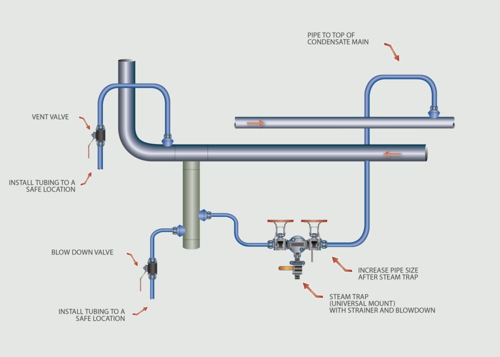
The steam line drip leg pockets need to be properly sized, properly installed, and have a proper steam trap station for condensate removal. Manual blow down line should be provided at the side of the steam line drip pocket for proper condensate and air removal at start-up in the plant startup procedures.
2. Key Factors
2.1. Steam Line Drip Leg Pocket Size:
A drip leg pocket that is a properly sized will remove the “drips” of condensate that will form in the steam line due to thermal losses.
Sizing should be as follows;
- 2 in. steam line = 2 in. drip pocket
- 3 in. steam line = 3 in. drip pocket
- 4 in. steam line = 4 in. drip pocket
- 6 in. steam line = 6 in. drip pocket
- 8 in. steam line or above = one pipe diameter smaller than the steam line for the drip pocket
2.2. Lengths
- At least 12 in. or more for the vertical drip leg pocket length to the steam trap station connection
- 3” below the steam trap station connection for the installation of the blow off valve connection
a. Blow off valve for condensate removal at startup

b. Venting air at startup
c. Blow off valve to be mounted on the side of the drip leg pocket – not off the bottom
2.3. Air Venting
All steam line must have manual or automatic air vent devices to remove air during start-up. If the system has no air venting capability, then all the air is in the steam line at start-up will flow into the process equipment.
Best Practices
The effects of water hammer cannot be underestimated, as its forces have been documented to be capable of the following results:
- Proper condensate removal on all steam lines
- Select reliable steam traps for the steam drip pockets.
- Use universal mount steam traps for this application
- Air vents on all steam line lines (manual or automatic)
- All steam traps should have an internal strainer or external strainer
- Use ball valves with a Class Four shutoff or higher for isolation.
- Tubing for installation will eliminate leak


