No. 24 – Steam Heat Transfer Components
Do you want this article in PDF format? Download it here:
Download a PDF1. Summary
Twelve primary factors affect the performance, longevity, and ongoing maintenance requirements for steam heat-transfer components. Generally, a steam component should be evaluated in terms of a 10-year operational life cycle. The proper selection of a component first requires a full understanding of the operational characteristics of the system where the steam component will function.
The plant should conduct a thorough review of the steam system’s operating parameters, reliability requirements, and documentation. Failing to understand the total context of the application commonly results in improperly sized and misapplied steam heat-transfer components.
In addition to understanding the application, plant personnel must also be familiar with all pertinent codes and design specifications. TEMA, ASME, API, and B31.1 are some of the codes and standards that personnel should review to ensure safety and proper operation. Adhering to appropriate installation recommendations for steam components will eliminate premature failures, enhance the likelihood of proper performance, and ensure the longevity of the heat-transfer units and the associated components.
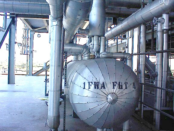
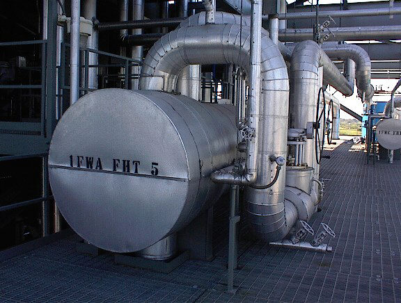
Figure 1. Shell and Tube Installation
2. Overview of Heat Transfer
Failing to employ fundamentals and not establishing the appropriate specifications for selecting the correct steam heat-transfer components are just some of the factors that lead to premature failure or underperforming heat-transfer results.
Inveno engineers have reviewed numerous industrial heat-transfer applications in various locations and industries. Based on their experience, what follows is a list of the most common problems caused by incorrect component selection or improper installation practices:
- unacceptable product quality,
- premature failure of components,
- poor temperature control,
- water hammer,
- low process temperatures,
- fouling of the heat-transfer equipment, and
- code violations.
3. Best Practice Guidelines
The common problems listed above may be avoided by following some simple rules and field-proven techniques. The best practices listed below should be reviewed and implemented into the steam system design, maintenance, and specification program for each facility.
3.1. Specifying the Correct Steam Pressure

Figure 2. Heat Exchanges in a Process Hunt
Too many plants specify the operating steam pressure of the steam distribution system, which is a major error due to the pressure drops that can result in the system. For example, if you specify an operating pressure of 150 psig and the heat-transfer unit was designed for the temperature of 150 psig steam (366°F), then the plant needs to supply the correct pressure to the heat-transfer unit to ensure proper operation. But, due to pressure drops in the steam line and pressure drops across the steam valve, the heat-transfer unit will never receive the 150 psig or 366°F steam temperature. For more information on the correct steam pressure for the process, see the Best Practice on Specifying the Correct Steam Pressure.
3.2. Steam Control Valves and the Condensate Drip Leg
A steam control valve is a modulating component in the steam system. Low or no steam flow to the process will result in the buildup of condensate prior to the inlet of the steam control valve. Condensate that accumulates before the steam control valve that will pass through the valve can cause premature failure of the valve and, in severe cases, water hammer that will damage the heat-transfer unit. The buildup of condensate can be eliminated simply by installing a drip leg pocket prior to the inlet of steam control valve. This allows the condensate to fall into the steam line drip leg pocket and be evacuated with the assistance of a steam trap station.

Figure 3. Heat Transfer Installation Guidelines
3.3. Lockout Ball Valves
The use of ball valves can provide a tight shutoff (Class 4 or higher) for steam service, and a few steam ball valves come with a lifetime warranty. All ball valves should be purchased with locking handles for the best safety procedure (lockout–tagout). Check with the designated safety personnel at the plant to ensure valves are in compliance with any company rules or federal, state, or local regulations concerning lockout–tagout procedures.
3.4. Install a Strainer Ahead of the Control Valve
Foreign particles may become prevalent in a steam line due to corrosion. This material can lodge in the control valve trim, causing premature failure of the steam control valve. A strainer will act as a filter and prevent any foreign or corrosion material from entering the steam valve.
When installing the strainer, always install a blow-off valve with a locking handle on the strainer, and pipe the discharge from the valve to a safe location.
Always install the strainer with the strainer section in the horizontal position, as detailed in the installation drawing. Never install the strainer with the strainer section vertical.
A 20-mesh strainer should be sufficient to filter the corrosion material.
3.5. Turndown and Control Valves
Several factors are relevant when selecting control valves. A primary one is the turndown capability or operation performance range of the steam control valve. Following are some guidelines for steam control valves. Heat-transfer components require properly sized control valves for proper process temperature control (based on the heat sink principle).
- Regulating valve: 20:1 turndown ratio
- The lowest turndown of any steam control valve
- Globe control valve: 30:1 turndown ratio
- Cage control: 40:1 turndown ratio provides the highest degree of controllability
- V-ball control valve: 70:1 or better turndown
3.6. Install Pressure Gauges Before and After the Control Valve
Pressure gauges provide valuable information needed to understand the steam conditions around the steam heat-transfer component. The pressure information is necessary for benchmarking the performance of the heat-transfer unit. Pressure gauges allow for troubleshooting if any problems occur in the system. Additionally, all pressure gauges should be installed with a siphon pipe (pigtail) and isolation valve (see Best Practice on Pressure Gauge Pigtails).
3.7. Air Vents (Manual or Automatic)
The existence of air or noncondensable gases in a steam system has several detrimental effects on heat transfer. Noncondensable gases in the system can form films on heat-transfer surfaces and greatly reduce the heat-transfer unit’s ability to absorb the heat energy from the steam. Air is a very efficient insulator. (Its thermal conductivity is 0.2.) A film of air of only 1/1000 of an inch has the same effect as a thickness of 13” of copper or 3” of cast iron.
Not only does air insulate, but it also reduces the heat-transfer rate by lowering the temperature of the steam. The saturation temperature of steam is reduced when it is mixed with air in accordance with the law of partial pressures. Air contributes to the pressure of the mixture but does not contribute to the available heat content.
All heat-transfer units should have either manual air vents (that are operated with standard operating procedures) or automatic air vents.
3.8. Saturated Steam Versus Superheated Steam
Typical steam applications require a steam quality of 100% at saturated steam conditions. This level of steam quality refers to steam containing no minute droplets of condensate entrained in the vapor. The addition of any superheated steam to a heat-transfer process can cause performance problems if the original design did not anticipate superheat in the steam. Furthermore, superheated steam may require material changes to handle differences in the pressure and the temperature of the steam.
3.9. Condensate Removal
When designing heat-transfer units, condensate drainage is accomplished in most applications by gravity. In a few applications, the use of pressure differential with the use of siphon joints accomplishes the condensate drainage. Heat-transfer equipment should be installed to promote gravity drainage with no vertical lift before or after steam traps if the discharge product temperature is below 220°F. To ensure proper drainage in these applications, it is extremely important to the condensate drain device (control valve or steam trap station) to discharge into an atmospheric or zero pressure condensate return system. This is because the modulating steam control valve can operate at very low percentages of valve travel and deliver very low steam pressures to the process.
Numerous premature failures and performance problems can result from unanticipated backpressure on the drain devices, which causes condensate to accumulate in the heat-transfer unit. This will result in water hammer and inadequate temperature control. Poor condensate drainage can also result in corrosion problems for the heat-transfer unit. The horizontal distance from the vertical drop leg (condensate outlet of heat exchanger) to the steam trap station should never be more than 8 inches. Any length of pipe longer than 26” can lead to steam locking. Install a test valve or a visual sight glass after the steam trap for a visual indication of performance.
3.10. Insulation
All exposed surface areas in a heat-transfer application should be insulated. Please refer to the U.S. Department of Energy’s Best Practices Steam Tip Sheet on insulation for further details on payback and material selection.
3.11. Control Valve Piping
The sizing and length of pipe from the control valve outlet to the inlet nozzle on the heat-transfer unit is critical. Control valve outlet piping must be increased to be equal to or larger than the inlet connection to the heat-transfer unit.
The control valve should be located at least 10 pipe diameters away from the heat-transfer unit with the expanded pipe.
3.12. Vacuum Breakers
All heat-transfer components, whether shell-and-tube, plate-and-frame, or any other device, require vacuum breakers. Vacuum breakers protect heat-exchanging equipment when a system is shut down by preventing a vacuum from occurring. Additionally, the vacuum breaker maintains the condensate in the heat-transfer equipment. It is generally recommended that all heat-transfer devices have an air vent and vacuum breaker installed at points designated by the heat-transfer manufacturer. The normal locations are close to the steam inlet or on the top portion of the heat-transfer unit.
3.13. Fouling Factors
Fouling is a function of the steam system and the process equipment used in the steam system. Parameters that influence the fouling rate in a system include the type of process fluid, the type of heat exchanger, the process and steam temperatures, the velocities, and the materials of construction. The actual fouling rate is different for each steam application.
There are numerous resources for fouling factor values. During the selection process, be sure to specify the fouling factor.
3.14. Codes and Standards
As mentioned earlier, all relative jurisdictional codes must be known and followed during design, engineering, selection and installation.


