No. 21 – Flash Steam Vent Condensers
Do you want this article in PDF format? Download it here:
Download a PDFBEST PRACTICE NO. 21
FLASH STEAM VENT CONDENSERS
OVERVIEW
With today’s energy pricing and the need to reduce emissions, a plant’s steam/condensate systems cannot afford to vent flash steam to the atmosphere. The modulating steam system’s operational design requires the condensate to be recovered by a gravity (0 psig) condensate system. A typical system will incorporate a condensate receiver that allows the flash steam to vent to the atmosphere. The venting of the flash steam ensures the condensate receiver is never pressurized. To prevent the flash steam loss to the atmosphere, plants install devices such as flash steam vent condensers in the flash steam vent line.
Depending on the installation costs, plants will typically recover the cost of a flash steam vent condenser within 10 operational months. The cost-saving benefits a flash steam vent condenser offers include allowing a plant to recover the flash steam energy, which it can use to heat a fluid for a process. The other benefit is reducing emissions: by recovering the flash steam energy, the boilers will have to produce less steam, lowering emissions from the boiler operation.
2. FLASH STEAM RECOVERY SYSTEMS (MODULATING STEAM CONDITIONS)
If the condensate/flash steam (two-phase flow) is being discharged from a modulating steam/condensate process, it means the process application has a steam control valve modulating the steam to the process and the control valve can operate from 0% (closed) to 100% (full open) and anywhere in between. (See Figure 1.) The steam pressure after the steam control valve and before the process heat exchanger can vary (P2 reading) depending the process conditions. The pressure at P2 can range from the full line pressure being delivered to the steam control valve (P1) all the way down to 0 pressure.

Figure 1: Steam Control Valve
In this case, the flash steam cannot be recovered in a pressurized flash tank or high-pressure condensate return system. Instead, the condensate flow from the process has to be discharged into a condensate line with pressure at 0 psig (P5) and delivered to a vented condensate receiver tank that is operating at or close to 0 pressure.

Figure 2: Typical Condensate Receiver Tank
Figure 2 depicts the typical condensate receiver tank arrangement, where the flash steam is allowed to be vented to the atmosphere. The energy loss and emission factors today permit this loss in the system.
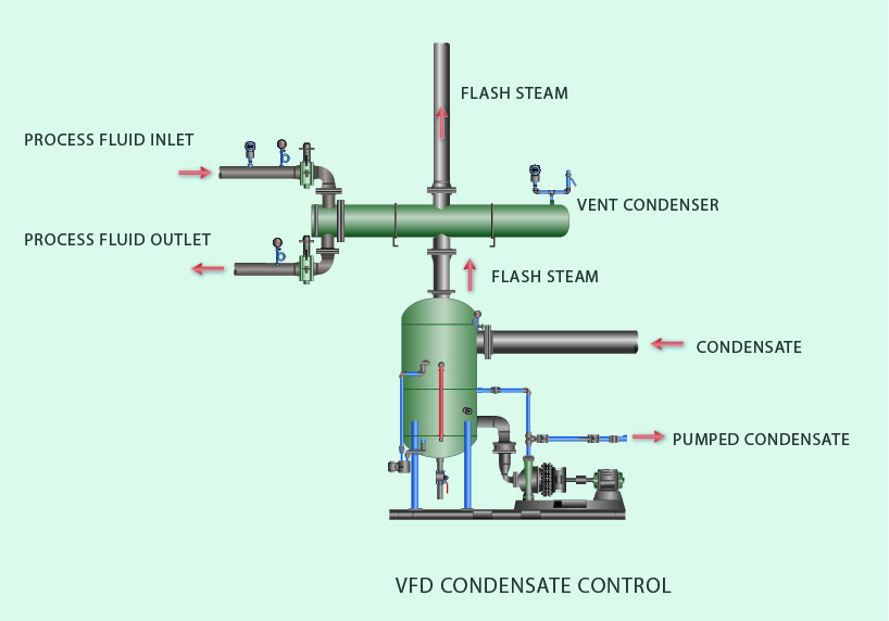
A flash steam vent condenser is incorporated in the system to recover the flash steam by using an external heat exchanger (condenser), as shown in Figure 3. The vent condenser (heat exchanger) will consume the flash steam by heating air, water, or some other process fluids. The vent condenser is designed for the application to ensure proper operation. A standard shell-and-tube heat exchanger functions in this application. The process fluid consumes the flash steam and allows the condensate to drain back into the condensate tank. Therefore, the flash steam is consumed and the condensate is recovered. In the case of a modulating steam process condition, the process steam system should use the lowest steam pressure, therefore producing the least flash steam possible.

Figure 3: External Heat Exchanger (Condenser)
3. FLASH STEAM CONDENSER
The shell-and-tube heat exchanger designed for a condenser application is the typical heat transfer design used in flash steam condensers. Other heat exchanger units that can be used are spiral, plate and frame, and fin coil units (heating units for air or process gases). Materials and installation considerations will vary depending on the application. All vented condensers are engineered for the application.
3.1. Fluid for the Condenser
To condense the flash steam, the condenser requires a fluid temperature of less than 160°F (general consideration). The fluid can be a liquid or vapor, depending on the application. If there is an insufficient quantity of cooling fluid for the flash steam in a liquid cooling system, then the plant should consider using a flash steam bypass or some other method to prevent the cooling liquid from absorbing too much energy and changing from a liquid to a vapor and causing water hammer.
Heating air is another application for a vent condenser. Figure 4 shows the air passed over a tube fin configuration with the flash steam inside the tube. The lower temperature air condenses the flash steam, and the condensate is allowed to drain back into the condensate tank.

Figure 4
3.2. Pressure on the Condensate Tank
When choosing a vent condenser, the plant must select a design that does not create significant pressure for the condensate receiver tank. The flash steam vent line from the condensate tank to the condensing unit velocities should not exceed 900 feet per minute.
3.3. Required Information
To have a successful vent condenser purchase, installation, and operation, the plant should know the following parameters:
- Condensate flow rate
- Maximum
- Minimum
- Normal
- Flash steam flow rate
- Maximum
- Minimum
- Normal
- Cooling fluid flow rate
- Maximum
- Minimum
- Normal
4. ROAD MAP
- Find and document the different flash steam vent lines that are discharging to the atmosphere.
- Determine the flash steam lost to the atmosphere.
- Calculate the projected energy loss and emissions reduction.
- Determine what types of cooling fluids are available.
- Install a condensate tank with a vent condenser.


