Condensate Pumping System Design – Best Practice No. 2
Do you want this article in PDF format? Download it here:
Download a PDFBEST PRACTICE NO. 2
Selecting the Correct Pumping System
Capacity required
- Maximum
- Minimum
- Normal
Tank sizing
- Flash steam, neglect of the steam system
- Required discharge pressure
- NPSH required due to the temperature of the condensate
- Control of the flow of condensate
- On/off or continuous flow
Vent sizing
- If receiver is vented to atmosphere
- Location and installation
The plant needs to document the required capacity of the condensate pumping system. Condensate pumps are used in a variety of process and heating applications. The maximum load is never usually achieved and there is typically a great variance between the normal high condensate flow and the minimum condensate flow. Therefore, careful consideration must be given when defining the condensate capacity.
2. Sizing of Receivers
The receiver should be sized for capacity sufficient to allow condensate storage for a minimum of 15 minutes. “Best Practice” is to have 30 minutes of storage.
Example:
- 4,000 lbs. per hour (condensate capacity)
- 4,000 divide by 8.3 (lbs per gallon) divide by 60 (minutes in an hour) = 8.03 gpm
- 8.03 gpm x 15 = 120 gallon storage tank
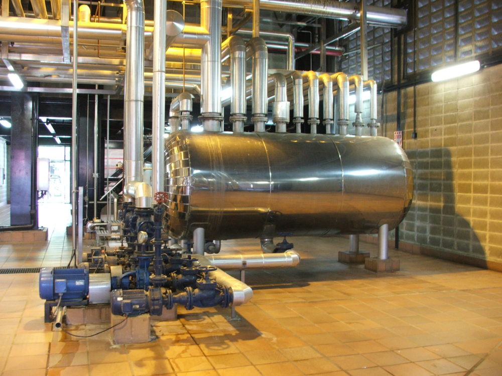
The tank material is typically a heavy wall steel tank or a stainless steel. In some cases, the tank is coated with a corrosion-resistive material.
It is recommended that the tank be stamped ASME, even if the tank is vented to atmosphere, to provide a more desirable tank construction for industrial applications.
Rectangular Tank Capacity (C in Gallons)
C = Height x Width & length (inches)
230
Or
C = HWL (Ft.) x 7.5
Storage Capacity of Circular Tanks in gallons
Circular tank diameter-(D) in feet
Length – (L) in feet
Storage = 6D² x L (gallons)
3. Selecting an Electrical Condensate Pump to Prevent Cavitation
A critical factor that should be investigated in the selection of a condensate pump is the NPSH. This is extremely important when choosing a condensate pump due to temperatures in condensate systems are above 212oF.
NPSH is determined by factors such as temperature, altitude, static head, and capacity. Condensate pumps are available that have been specifically designed to handle low NPSH, preventing cavitation, and thus able to operate at higher temperatures.
3.1 Cavitation
As liquid enters the eye of the impeller in a centrifugal pump, its pressure is reduced. If the absolute pressure at the impeller eye drops down to the vapor pressure of the fluid, vapor pockets begin to form. As these vapor pockets travel in the fluid along the vanes of the impeller, pressure increases and the pockets collapse.
This collapsing of the steam bubbles is called cavitation.
Cavitation is not only noisy but also damages the pump impeller, shaft and seal, and, over time, may reduce pumping capacity. NPSH refers to the minimum suction pressure, expressed in feet of water column, that is required to prevent the forming and collapsing of these vapor pockets.
The diagram shows the change in system pressure (Ps) as the fluid travels through the impeller. To prevent cavitation, Ps must remain above the vapor pressure. The top curve shows system pressure (Ps) remaining above fluid vapor pressure as it passes through the pumps; cavitation cannot occur. The bottom curve shows Ps falling below the vapor pressure as it enters the impeller eye. This will cause cavitation. The cutaway view of a pump on the picture shows the passage of flow through the impeller.
3.2 NPSH is determined by factors:
- Temperature
- Altitude
- Static head
- Capacity
NPSH = Barometric Pressure, Ft. + Static Head on suction,ft. – friction losses in suction piping, ft. – Vapor Pressure of liquid, ft.
Defined as a suction pressure minus vapor pressure expressed in feet of liquid at the pump suction. Results from the height of water above the pump suction.
Suction Head = Total Pressure of Liquid Entering the Pump Suction
3.3 Two Values of NPSH
There are two values of NPSH: NPSHR and NPSHA.
NPSHR (required) is the amount of suction head required to prevent pump cavitation, is determined by the pump design, and is indicated on the pump curve. It varies between different makes of pumps, between different pumps of the same design and varies with the capacity and speed of any one pump. This is a value that must be supplied by the maker of the pump.
NPSHA (available) is the amount of suction head available or total useful energy above the vapor pressure at the pump suction. This is determined by the system conditions. NPSH typically is measured in ft of liquid.
3.4 Calculating NPSHA
NPSHA, measured in feet, can be calculated by using the equation noted below. The vapor pressure of the liquid is subtracted from the system pressure Pa. It is then converted from psia to feet by multiplying by 2.31 and dividing by the specific gravity of the liquid. The static head He measured in feet is determined by the elevation of the water line above the pump suction. This value can be negative if the application is a suction lift. Finally the friction losses, Hf, measured in feet, are calculated and subtracted from He. This quantity is then added to the first term of the equation.

Where
Pa = Pressure in the receiver, psia
Pv = Vapor pressure of the liquid at its maximum temperature, psia
He = Elevation head, ft.
Hf = Frication losses in the suction piping at the required flow rate, ft
Spgr = Specific Gravity
The following is an example of the calculation of NPSH. 100 gpm of condensate is returning at 210 F to a receiver that is vented to atmosphere. The static suction head is 2 ft. Pressure drop through the pipe is calculated for 1 ft of 2-1/2 in .pipe with a 90 deg elbow and a gate valve. The friction loss through a 2-1/2 in. iron pipe is 7.1 ft per 100 ft of pipe. The equivalent length of straight new pipe for turbulent flow has to be calculated for the elbow and valve. The 90 deg elbow has an equivalent length of 3.6 ft and the gate valve has an equivalent length of 1.7 ft. The total equivalent length is summed and multiplied by 7.1 ft per 100 ft. The calculated NPSHA for this example is 2.99 ft. The pump that is selected for this example must have a NPSHR less than 2.99 ft to prevent cavitation from occurring (Fig. 2).
3.5 Pounds Pressure versus Feet of Head
Each pound of pressure developed by a pumping system is equal to 2.31 feet of head. Therefore, 10 pounds of pressure (PSI) will lift water vertically 23.1 feet.
This can be calculated for any setting using the following formula:
Pounds per sq. in. = Head in Feet
2.31
Head in Feet = Pounds per sq. in. x 2.31
4. Vent Sizing for Condensate Tanks
The vent for the condensate tank should be sized for the amount of flash steam. Please refer to the flash steam tables in the first chapter. Also, the vent must have added capacity for live steam that may occur from a poorly managed steam system.


