Steam Locking or Binding – Best Practice No. 12
Do you want this article in PDF format? Download it here:
Download a PDFstrong>BEST PRACTICE NO. 12
STEAM LOCKING OR BINDING
In today’s steam operations, steam locking (also called steam binding) is seldom detected or diagnosed as the root cause of system problems. Instead, problems are almost always blamed on a malfunctioning steam trap. However, steam locking is not a new problem in steam system operation; in fact, it was written about in detail in a steam engineering manual back in 1939.
1. WHAT IS STEAM LOCKING?
A steam trap is a simple device. It senses three things: steam, condensate, and non-condensable gas or air. If the steam trap senses steam (vapor) is present, the steam trap will shut off to prevent steam from passing through. A steam trap in good operational condition will only open to allow the flow of condensate that has been generated and will close when steam enters the steam trap.

Figure 1: Steam Trap with 26″ of Horizontal Pipe
If a steam trap is installed with a length of horizontal pipe (26”) or longer from the vertical discharge condensate pipe of the condensate outlet of the steam process, steam locking will occur.
With the steam trap in a closed position to prevent steam loss, the long horizontal pipe (26” or longer) will be momentarily be filled with steam. Therefore, condensate will not be able to flow to the steam trap due to its inability to displace the steam vapor that has accumulated in the horizontal line. After a period of time, the steam in the horizontal pipe will condense due to heat losses from the condensate pipe, and the condensate will then be allowed to flow to the steam trap. The steam trap will sense the condensate and allow the condensate to flow through the steam trap into the condensate header.
During the period of steam locking of the system with the steam trap in the off position, condensate will back up into the heat transfer, steam line drip leg, or any other steam component, and this action will negatively affect the process.
The negative effects of steam locking are as follows:
- water hammer, which causes premature component failures;
- loss of process temperature;
- low steam quality;
- process temperature control fluctuations; and
- corrosion
2. ROOT CAUSE ANALYSIS INDICATIONS OF STEAM LOCKING
Water hammer is typically present in steam locking situations. Water hammer will cause premature failures in steam system components. The results of water hammer are downtime and loss of reliability of the equipment.
Poor temperature control or fluctuations in the process are another indication that condensate is backing up into the process. Condensate only has sensible heat, which is low in Btu content, when compared to steam, which has high heat content.
Condensate backing up from steam locking can cause freezing in areas where outside temperatures will be below 32°F.
3. ROOT CAUSE ANALYSIS CHECKS
If a test valve is installed before the steam trap or the strainer blowdown valve, upon opening the valve to the atmosphere, there will be very little or no condensate flow followed by a very large increase in flow of condensate. Essentially, the opening of the test valve or strainer valve releases the steam locking and allows condensate to flow to the steam trap. This can also be done by opening any drain valve between the steam trap and the process condensate outlet.
Temperature profiling of the application will also provide temperature variances, which indicates steam locking.

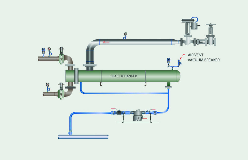
Figure 2: Balancing Line for a Steam Trap with a Connection Port and Balanced to the Condensate Outlet

Figure 3: Steam Balancing a Steam Trap back to the Process
3.1 Solutions
- Keep all horizontal lines from the vertical condensate pipe from the process outlet to the steam trap less than 26”.
- If this is not possible due to installation constraints, then add a steam balancing line as shown in the piping configuration below. Figure 2 indicates a simple addition of a balance line that can eliminate any system problems with steam locking.
- Figure No. 3 shows the balance line being connected to the heat transfer unit.
Correct installations will ensure proper operation of the system.


