Best Practice No. 11 – Steam System Waterhammer Causes and Solutions
Do you want this article in PDF format? Download it here:
Download a PDF1. STEAM AND CONDENSATE WATERHAMMER
Water hammer is never normal in the steam and condensate system and must be always considered extremely abnormal and totally unacceptable in today’s plant operation. Water hammer is not only a system issue; it is primarily a safety issue. Understanding the nature and severity of water hammer in a steam and condensate system will allow plants to avoid it’s the safety issue and destructive forces.
A greater understanding of steam system waterhammer will help the plant to implement the necessary changes in steam system design, start-up, maintenance, operation and installation to eliminate waterhammer. This will additionally help provide maximum safety for plant personnel, reduce maintenance cost, and reduce system downtime.
In its most severe form, water hammer can injure or even cause fatalities to plant personnel.
Unfortunately, 82% of the steam systems in North America are experiencing some type of water hammer. Many mistakenly believe that water hammer is unavoidable and a natural part of steam and condensate systems but this statement is entirely false. If the system is properly designed and correctly operated, water hammer in any form will not occur. It is possible to have high-pressure steam systems operating without water hammer and enjoy a long operational life from the steam components.
In Figure 1, the red circles show improper connection to the condensate header which will generate a thermal shock type of waterhammer. Instead of connecting into the side of the condensate header, the returns should enter in the top of the manifold (condensate header).
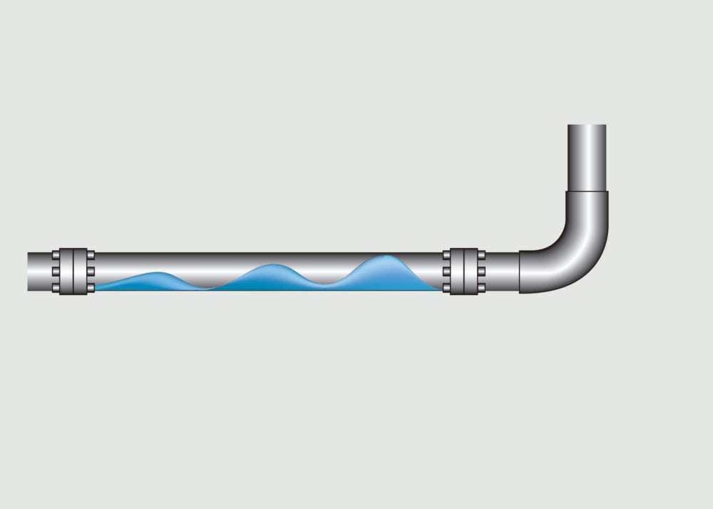
Figure 1: Water Hammer
2. WHERE DOES WATER HAMMER OCCUR?
Water hammer can occur in any steam or condensate line. The steam system is greatly at risk of waterhammer during startup of the steam system when the highest level of condensate is generated during the warm up of the steam line. If the steam line is energized too quickly without proper warm-up time, and if the condensate created during the start-up is not being properly removed, water hammer will result.
The other risk of waterhammer in the steam system is when the condensate is not properly removed from the steam line during operation.
Its effects can be even more pronounced in heterogeneous or condensate bi-phase (flash steam and liquid condensate) systems. Condensate bi-phase systems contain two states: the liquid (condensate) and a vapor (flash or generated steam). The bi-phase condition exists in a steam system where condensate coexists with generated flash steam.
Typical examples include heat exchangers, tracer lines, steam mains, condensate return lines, and sometimes pump discharge lines.
3. RESULTS OF WATER HAMMER
The effect of water hammer cannot be underestimated, as its forces have been documented to be capable of the following results:
- Rupturing pipe fittings
- Causing valve failures
- Causing heat exchanger equipment failures
- Breaking pipe welds and even rupturing piping systems
- Causing the failure of pipe supports and guides
- Bending internal system mechanisms
- Flange failures
- Overstressing pressure gauges
- Cracking steam trap bodies
When water hammer is severe, it can result not only in damage to equipment but also in significant injury to plant personnel.
Water hammer may be occurring and yet be silent to personnel. This means water hammer is not always accompanied by audible noise that the human ear can hear. For example, a steam bubble from flash steam that is delivered into a condensate line under the condensate level in the piping system may be small, yet the collapsing bubble creates a thermal shock that is beyond the range of human hearing. However, the damage to steam and condensate system is still occurring.
The continuing banging or audible sound accompanying water hammer should be interpreted as the way the steam system is trying to communicate with plant personnel. This audible noise should be an alarm meaning “please correct the system errors to eliminate the water hammer problem, or damage will occur.” This water hammer sound means something in the system is wrong and needs to be corrected.
Evidence gathered while conducting root cause analysis on steam component failure suggested that water hammer causes 67% of premature component failures.
4. CONDITIONS CAUSING WATER HAMMER
There are four typical conditions have been identified as causes of the violent reactions known as water hammer. These conditions are:
- Hydraulic shock
- Thermal shock
- Flow shock
- Differential shock
The technical paper will provide a description of each of these causes.
4.1 HYDRAULIC SHOCK
A small percentage of the water hammer problems found in a steam system are caused by hydraulic shock. This type can be easily described by using the example of a home faucet. When the faucet in a home opens, a solid shaft of water is moving through the pipes from the point where it enters the house to the outlet of the faucet. This could be 200 pounds of water moving at 10 feet per second or about seven miles per hour. When the faucet is suddenly shut, it could be compared to a 200-pound hammer coming to a stop. There is a noticeable “bang” heard in the system when the faucet is closed. This shockwave sound is similar to a hammer hitting a piece of steel. The shock pressure wave of about 300-psi is reflected back and forth from end to end until the energy is dissipated in the piping system.
This is the same action that can take place in the discharge piping in a condensate pump system. When pumps (electric or steam motive) are used in an on/off operation with large condensate pumping capabilities. The pumping system normally have check valves installed on the pump outlet. As the pump starts and stops, hydraulic shock can occur as the condensate flow rapidly stops and the check valves restrict the flow in one direction.
Solutions:
- Condensate capacities above 12,000 lbs. per hour use a continuous flow pumping system that incorporates a variable speed drive motor or a level control valve in the discharge line of the condensate pump (pump operates continuously).
- Use disk type check valves on the pump discharge instead of the common swing type.
4.2 Thermal Shock
One pound of steam at 0 psig occupies 1,600 times the volume of a pound of water at atmospheric conditions. This ratio drops proportionately as the condensate line pressure increases. When the steam collapses, water is accelerated into the resulting vacuum from all directions with great speeds.
In bi-phase condensate systems, steam bubbles may be introduced below the level of condensate in a condensate line. For example, a branch line from a steam trap station may be piped to the bottom of a condensate main header. As shown in figure no. 2.

Figure 2: Incorrect Condensate Piping
Example: Steam is introduced into the heat exchanger (P2) at 100 psig or 338oF and condensate at P3 will be 338oF. When the condensate passes through the steam trap station at P4, which at a lower pressure a percentage of the liquid will flash to steam due to the low pressure/temperature relationship. When the flash steam bubble flows to P5 and is introduce below the condensate level in the condensate piping; the thermal differences will cause the flash steam bubble to collapse. During the collapsing, the water is accelerated an extremely high speed due to the vacuum that occurred when the bubble collapsed. The result is a pinging sound or when there is large quantity of flash steam (bubble is large) a very sharp banging sound.
Solutions: Connecting into the Condensate Header
All condensate system branch lines must be connected into the top of the main condensate header: there is no exception. The condensate connection is at the top on the horizontal condensate main header and never into a vertical condensate header.

Figure 3: Connecting Into the Condensate Header
Figure 4: Proper Piping
4.3 Flow Shock
Flow shock is most commonly caused by lack of proper drainage ahead of a steam line isolation valve or steam control valve. For example, consider a steam line isolation valve (typically used with pipe of 3” or larger) opened without the use of a warm-up. When the large valve is opened, steam rushes down a cold pipe, producing a large quantity of condensate at high velocity. This condensate will continue to build in mass as it travels along the pipe, and a large wave of condensate is created. The wave will travel at a high velocity until there is a sudden change in direction, possibly an elbow or valve in the line. When the condensate changes direction, the sudden stop will generate water hammer.
When a steam control valve opens, a slug of condensate enters the equipment at a high velocity. Water hammer is produced when the condensate impinges on the heat exchanger tubes or walls.
Solutions:
- Installation and use of a warm-up valve that is shown in figure no. 3.
- Installation of a steam line drip leg pocket with a steam trap station ahead of the isolation valve.
These recommendations will prevent water hammer during start-up, but it will also promote long valve life.
4.4. Differential Shock
Differential shock, like flow shock, occurs in bi-phase systems or the condensate system. It occurs whenever steam and condensate flow in the condensate line but at different velocities. In bi-phase systems, the velocity of the steam is often ten times the velocity of the liquid. If condensate waves rise and fill a pipe, a seal is formed temporarily between the upstream and downstream side of the condensate wave. Since the steam cannot flow through the condensate seal, pressure drops on the downstream side. The pressure differential now drives the condensate seal at a high velocity downstream, accelerating it like a piston. As it is driven downstream, it picks up more liquid, which adds to the existing mass of the slug, and the velocity increases.
Just as in the example above, the slug of condensate gains high momentum and will be forced to change direction due to an elbow or a valve in the line. The result is usually great damage when the condensate slug pounds into the wall of a valve or fitting while changing direction.
Since having a bi-phase mixture is possible in most condensate return lines, correctly sizing condensate return lines becomes essential. Condensate normally flows at the bottom of a return line with the assistance of gravity. Condensate flows naturally because of the pitch in the pipe and also because the higher-velocity flash steam above it pulls it along. The flash steam moves at a higher velocity because it moves by differential pressure.
Flash steam occurs in the condensate return lines when condensate discharges into these lines that are operating at a lower pressure. The lower pressure causes a percentage of the condensate to flash back to steam at the given saturation pressure. If the lines are also undersized, additional pressure is created in the line. This pressure pushes the flash steam at relatively higher velocities toward the condensate receiver, where it is vented to the atmosphere.
Heat loss of the flash steam while moving in the line causes some of the flash steam to condense, which contributes to this pressure difference and amplifies the velocity. Because the flash steam moves faster than the condensate, it makes waves. As long as these waves are not high enough to touch the top of the pipe and do not close off the flash steam’s passageway, there is no problem. This is why larger condensate return lines are preferred. To control differential shock, the condensate seal must be prevented from forming in a bi-phase system.

Figure 5: Flow Shock

Figure 6: Differential Shock
Condensate line velocities (two phase flow) should never exceed 4,500 fpm. If the condensate line is properly sized for the liquid and flash steam, but the plant does not have a proper steam trap management program and steam traps are failed and blowing steam into the condensate line, this will contribute to increase velocities above 4,500 fpm and waterhammer will occur in the system.
Solutions:
- Condensate lines sized for 4,500 fpm or less
- Steam trap station management program to eliminate unnecessary steam being introduced into the condensate line
5. OTHER METHODS IN PREVENTING OR RESOLVING WATER HAMMER
A variety of design or system changes can be implemented to prevent or eliminate water hammer:
- Implement proper training for plant personnel.
- Ensure correct steam and condensate design.
- Have documented standard operating procedures (SOPs) for steam system start-ups and shutdowns.
- Have installation standards for steam components.
- Specify and place steam line drip steam traps on the steam system properly.
- Correct condensate connections of branch lines to the main condensate line and enter only on the top.
- Use steam traps that are properly sized and appropriate for the application.
- Use warm-up valves on steam line isolation valves larger than 2 inches. Do not crack open large steam isolation valves with the hope of avoiding condensation-induced water hammer. This will not guarantee safe operation.
- Check or repair the pipe insulation. It saves energy and reduces accumulation of condensate in the piping system.
- Condensate line sizing is crucial to ensure proper operation of the steam system. Undersizing the condensate lines is one of the largest contributors to water hammer.
- All steam valves that can be in the closed position must have proper drip legs on the steam line to remove any condensate build up during the close position.
- Always direct condensate gravity drainage away from the process applications with a modulating control valve.
- Condensate can be drained into a pressurized condensate return line only if the proper differential is maintained.
- Properly label the steam and condensate lines.
- Remove abandoned steam and condensate lines from the system.

Figure 7. Standard Drip Leg Installation


